


 Flexible Thinking: Designing Flex Circuits for Dynamic Reliability
 Global PCB Connections: Rigid-flex and Flexible PCBs—The Backbone of Modern Electronics
 Happy’s Tech Talk #29: Bend-to-Install Semi-flex FR-4


Application: Design guidelines to improve the flexibility and reliability of flexible circuits.
Most issues that arise with flex circuits can be eliminated in the early stages of the design phase, and special planning must occur when the circuit is required to bend. Many novices will design a circuit that calls for bending the flex in too tight of a bend radius, which can cause damage to the circuit and lower the reliability of the end product. This is the third and final installment in a series of articles that will focus on the seven key aspects to consider when designing for maximum durability and maximum “flexibility." It is important to know that because flexibility is a relative term this study will instead use the term reducing bend radius. Below are three of the seven design strategies, please see Part I and Part II for more tips!
5. Apply strain relief at transition areas from stiffener to flex.
- Stiffener material is common in flex circuit designs that have soldered components. While this rigid material is necessary for the soldered components, it can cause reliability issues during installation when the flex is bent at the stiffener location toward the stiffener.
- If the flex material will be bending toward the stiffener, it is highly recommended that an epoxy bead of Ecobond 45 be applied.
6. Ensure vias are located at least .050” away from bend zones.

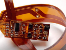
Fig. 1 - Examples of a flex circuit with a bend radius and a plated through-hole.
7. Always put a 3D representation of your bend to install configuration on your drawings.
- Many problems can be avoided by informing your flex circuit vendor what the final configuration is going to be once used, this enables them to evaluate for potential bend radius issues.
- Most flex circuit drawings are only 2D. By showing a picture of the final configuration you are encouraging the discussion regarding materials, discussion about minimum bend radius and letting the flex vendor raise any concerns before build.

Fig. 2 - Examples of a 3D drawing of a flex circuit.


