


 Driving Innovation: Mechanical and Optical Processes During Rigid-flex Production
 It’s Only Common Sense: Your Biggest Competitor Is Complacency
 The Chemical Connection: Onshoring PCB Production—Daunting but Certainly Possible


Decreasing Bend Radius and Improving Reliability- Part III
December 18, 2019 | Kelsey Smith, All FlexEstimated reading time: 1 minute
Application: Design guidelines to improve the flexibility and reliability of flexible circuits.
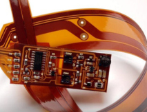
Most issues that arise with flex circuits can be eliminated in the early stages of the design phase, and special planning must occur when the circuit is required to bend. Many novices will design a circuit that calls for bending the flex in too tight of a bend radius, which can cause damage to the circuit and lower the reliability of the end product. This is the third and final installment in a series of articles that will focus on the seven key aspects to consider when designing for maximum durability and maximum “flexibility." It is important to know that because flexibility is a relative term this study will instead use the term reducing bend radius. Below are three of the seven design strategies, please see Part I and Part II for more tips!
5. Apply strain relief at transition areas from stiffener to flex.
- Stiffener material is common in flex circuit designs that have soldered components. While this rigid material is necessary for the soldered components, it can cause reliability issues during installation when the flex is bent at the stiffener location toward the stiffener.
- If the flex material will be bending toward the stiffener, it is highly recommended that an epoxy bead of Ecobond 45 be applied.
6. Ensure vias are located at least .050” away from bend zones.

Fig. 1 - Examples of a flex circuit with a bend radius and a plated through-hole.
7. Always put a 3D representation of your bend to install configuration on your drawings.
- Many problems can be avoided by informing your flex circuit vendor what the final configuration is going to be once used, this enables them to evaluate for potential bend radius issues.
- Most flex circuit drawings are only 2D. By showing a picture of the final configuration you are encouraging the discussion regarding materials, discussion about minimum bend radius and letting the flex vendor raise any concerns before build.

Fig. 2 - Examples of a 3D drawing of a flex circuit.
Share on:


Testimonial
"Our marketing partnership with I-Connect007 is already delivering. Just a day after our press release went live, we received a direct inquiry about our updated products!"
Rachael Temple - AlltematedSuggested Items
Industry Veteran Dr. Helen Song Joins Celera Semiconductor to Lead Product Design
10/28/2025 | PRNewswireCelera Semiconductor, the analog industry leader using AI to automate the entire product development flow, today announced that Dr. Helen Song has joined the company as vice president of Product Design.
Mapping the EV Landscape: Markets, Platforms, and Powertrains
10/28/2025 | Stanton Rak, SF Rak Companye-Mobility is the defining transformation of 21st-century transportation. As legacy OEMs, startups, and governments race to electrify vehicle fleets, the landscape of e-Mobility is expanding into previously unimaginable territory. But with innovation comes complexity, and with complexity, a need for systems that are not only high-performing but also reliably engineered for the long haul. Understanding the diversity and scale of the EV marketplace is essential to grasping the reliability challenges ahead.
Cadence Reports Q3 2025 Financial Results
10/28/2025 | Cadence Design Systems, Inc.Revenue of $1.339 billion, compared to revenue of $1.215 billion in Q3 2024
Elementary, Mr. Watson: Heat—The Hidden Villain of Power Electronics
10/28/2025 | John Watson -- Column: Elementary, Mr. WatsonIf electricity were a group of college students, then power electronics and the PCB designers who dive into it would insist on driving the car on every road trip because they know the car inside and out—they’re the students with jumper cables in the trunk, a tire pressure gauge in the glove box, and snacks stashed under the seat. While the others argue over playlists and directions, power electronics is busy ensuring the alternator doesn’t fry, the headlights don’t dim, and everyone reaches the destination with fuel still in the tank.
American Standard Circuits Launches 50th 77-Second Webinar
10/27/2025 | American Standard CircuitsAnaya Vardya, President and CEO of American Standard Circuits/ASC Sunstone Circuits is pleased to announce that they have recently unveiled their 50th 77-second webinar.