


 Standard of Excellence: Speed vs. Quality in Customer Service
 Knocking Down the Bone Pile: Revamp Your Components with BGA Reballing
 Global Sourcing Spotlight: Balancing Speed and Flexibility Without Sacrificing Control


Book Excerpt: 'The Electronics Industry’s Guide to… The Evolving PCB NPI', Chapter 3
January 4, 2023 | I-Connect007 Editorial TeamEstimated reading time: 2 minutes
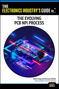
Chapter 3: Streamlining Data Preparation
With the need to move design data efficiently into manufacturing for assembly and test purposes, starting from a single source of intelligent data seems to be obvious. However, with different applications with different capabilities this can be difficult to achieve. Real-world support for any format can vary between machine and software vendors. The optimal goal should be to create a single digital twin of the product upfront regardless of the downstream applications that need that data.
If we consider the PCB and the parts being placed on it, their data should have significant commonality across the many steps in PCB assembly and test. Typically, we find that process and test engineers think there is much more machine-specific data across their lines than there really is in practice.
Solutions exist in the market that can manage this common data and then deliver machine-specific information to the machine software as needed, on demand. In this way, the factory can maintain the common data, but, more importantly, they have a common part library data that is independent of the line. Remember when we talked about the move from mixed vendor lines to single vendor lines and mixed-line factories? The ability to manage part data in this context is key to efficiently streamlining the NPI phase.
First, let’s start with the typical data preparation tasks that form the base for a typical NPI flow. Being able to accurately import the source layout CAD data is an important first step. As we discussed in chapter one, ODB++ and IPC 2581 provide a common, standardized data format for layout information. However, not all CAD data is the same, even in the context of one format such as ODB++. This is because different designers use unique conventions in their source libraries. The position and rotation of each component placement can be inconsistent for any single format because each component location is based on the definition of the library cell that it references. Why does this decrease efficiency?
Consider that, during the SMT process, the machine picks a component up from a feeder and positions that component, rotating it before releasing it on the board. What the machine considers for the rotation is based on its perspective and the orientation of the part in the feeder. However, what the design software considers for position and orientation is based on an arbitrarily defined cell library. The variations in that cell library are a result of the environment that the designer works in. What is the origin of the cell? Is it pin 1? Is it the middle of the part? Is it a corner on the cell? What is the rotation of the part at 0 degrees? Is it pin 1 to the left or to the right? What about IC components with many pins? Is pin 1 in the lower right corner, or maybe the lower left?
See Figure 3.1 for how a designer may have defined their source footprint, which is what is used for placement position and angle. We have a polarized part here but pin 2 is associated with the silkscreen indicator.
To continue reading this chapter of The Electronics Industry's Guide to... The Evolving PCB NPI Process, download your free book today!
Share on:


Testimonial
"Advertising in PCB007 Magazine has been a great way to showcase our bare board testers to the right audience. The I-Connect007 team makes the process smooth and professional. We’re proud to be featured in such a trusted publication."
Klaus Koziol - atgSuggested Items
TTCI Brings Hands-On Test Engineering and IPC Training Expertise to PCB Carolina 2025
10/31/2025 | The Test Connection Inc.The Test Connection Inc. (TTCI), a trusted provider of electronic test and manufacturing solutions, and The Training Connection LLC (TTC-LLC) will exhibit at PCB Carolina on Wednesday, November 12, 2025, at the McKimmon Center at NC State University in Raleigh, North Carolina. Attendees can visit Table 4 to say hello to Bert Horner and Bill Graver, and learn more about their test engineering services and technical training programs.
The Training Connection Continues to Grow with Addition of Veteran IPC Trainer Bill Graver
10/30/2025 | The Training Connection LLCThe Training Connection, LLC (TTC-LLC), a premier provider of test engineering and development training, is proud to announce the addition of Bill Graver to its growing team of industry experts. A respected professional with more than 35 years in electronics manufacturing, Bill joins as an IPC Master Trainer, bringing a wealth of hands-on experience in PCB testing, failure analysis, and process improvement.
Electronics Industry Warns Mexico Tariffs Could Undercut U.S. Manufacturing and Supply Chain Resilience
10/24/2025 | Global Electronics AssociationAs negotiations over U.S.–Mexico trade policies near an October 29 deadline, the Global Electronics Association released a new policy brief, From Risk to Resilience: Why Mexico Matters to U.S. Manufacturing.
Knocking Down the Bone Pile: Revamp Your Components with BGA Reballing
10/14/2025 | Nash Bell -- Column: Knocking Down the Bone PileBall grid array (BGA) components evolved from pin grid array (PGA) devices, carrying over many of the same electrical benefits while introducing a more compact and efficient interconnect format. Instead of discrete leads, BGAs rely on solder balls on the underside of the package to connect to the PCB. In some advanced designs, solder balls are on both the PCB and the BGA package. In stacked configurations, such as package-on-package (PoP), these solder balls also interconnect multiple packages, enabling higher functionality in a smaller footprint.
New Course Presents a Comprehensive Guide to IPC Standards
10/10/2025 | Marcy LaRont, I-Connect007Francisco Fourcade, electronics technology standards manager for the Global Electronics Association, has spent years helping companies understand and implement the standards that keep the electronics manufacturing industry moving forward. In this interview, he shares updates on ongoing standards development efforts and previews a new course, "IPC Standards: A Guide for the Electronics Industry,” which starts Oct. 14.