


 Learning with Leo: Drones—Meeting Demand Without Compromise
 Nolan’s Notes: Our Spotlight on North America
 Global Sourcing Spotlight: Building a Supply Chain That Bends, Not Breaks


AltiumLive Frankfurt 2019: Carl Schattke Keynote
December 5, 2019 | Pete Starkey, I-Connect007Estimated reading time: 4 minutes
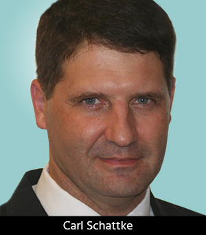
“How many here can remember manually taped artworks?” No more than three hands were raised in an audience of over 230 at the AltiumLive 2019 European PCB Design Summit in Frankfurt, Germany, as IPC Advanced Certified Interconnect Designer Carl Schattke introduced his keynote, entitled “Making and Breaking the Rules.”
Schattke had learned PCB layout as his father’s apprentice, hand-taping several hundred PCB designs in the 1970s and 1980s before becoming a CAD user with a Protel system—the precursor of Altium. He also ran a design bureaux , starting up a company designing acceleration systems for computer processing that was subsequently acquired by Intel. More recently, he has designed systems for advanced electric vehicles.
“If the design is possible, I can do it!” was Carl Schattke’s justifiable claim of capability, acknowledging that the manual experience gained in his early years gave him a positive advantage when tackling today’s complex designs. His objective had always been to achieve high reliability at low cost. Why rules? Schattke listed three points for discussion:
- Where have we been?
- What are the current issues with rules?
- Where do we see rules development going?
Tongue-in-cheek, he noted a quotation attributed to the Dalai Lama XIV: “Know the rules well, so you can break them effectively.”
So, where had he come from? What were the design rules that he had begun with? Schattke listed gridded Mylar, precision-slit tape (the choice of 15-mil, 30-mil, 50-mil, or 100-mil), photographic stickers for pads, working on the drawing board at 2x or 4x scale, followed by colour separation and camera reduction, measurement by ruler and monoscope, drill programming by bomb-sighting individual hole centres to produce NC tapes, fabrication drawings drafted manually and blueprinted, and design-rule checking by two people comparing the layout point-by-point with the schematic. Taping-up could take a couple of months. That all sounded familiar to PCB people of my generation, but most of us are retired or departed now, and that technology pre-dated most of the members of the audience.
“But then, this thing called CAD came along.” Schattke recounted some of the many shortcomings of crude-but-expensive early systems that had prompted him to revert to the traditional methods. “That was how we designed the computers that designed the computers that designed the computers we use now.”
It wasn’t until sometime later when Schattke tried the Protel system that he began to have any confidence in computer-aided design. That was 34 years ago. Protel developed into Altium Designer, and through several iterations, became the version in current use. Schattke commented that the company had always listened to the comments and suggestions of its users For example, Schattke had suggested automated the process of going from schematic to board, keeping track of everything along the way, and Altium did it.
One external factor that limited the scope of the early CAD systems was the capability of the available photoplotters—for example, the Gerber vector plotter with its D-codes, draws, flashes, and a 24-station physical aperture-wheel. But CAD succeeded in improving repeatability and reducing the skill level required to get a good result. And second-generation CAD tools were increasingly integrated, running on much faster computers, with more-complete libraries and interfaces to third-party tools, constraint rules, rules-driven routing, and software-driven rule writing, enabling increasingly complex design systems and enormous increases in design productivity.
What Schattke really came to talk about was rules. “How do we get our rules? How do we think about rules? How do we use rules? How does the software change with the rules that we use? And what kind of rules are we going to need in the future?” He reminisced about the days of making paper dolls to represent components, shuffling them around until the layout looked right and tacking them down while trying not to sneeze.
Where did the rules come from? Schattke referred to Altium’s constraint-based system and explained that rules could be either “unary,” which defined the required behavior of an object, or “binary,” which defined the interaction between two objects. He explained Altium’s set-up process, with examples of schematic-driven rules and PCB-driven rules, and asked the following questions: “What rules do we want to use, and what rules don’t we care about? When do we use rules, and when don’t we? How do we set the right rules, manage them, and validate them?”
Schattke discussed complicated clearance rules for high voltage and high current, special cases where clearances could be less than the rule, rules anomalies that caused occasional design-rule-ckeck failures, and rules not currently available that it would be nice to have, such as the distance to the return-path via for differential-pair transitions. The objective was always to achieve a clean design, free of design-rule-check violations.
Schattke listed some features of next-generation CAD tools: rapid integration of PCB and 3D mechanical design, rules-based routing, intelligent automation, intelligent peer-to-peer interchanges, rules-driven advanced library control and automation, seamless integration with task-specific design and checking tools—signal integrity, power integrity, design for manufacturing, design for assembly, electromagnetic compatitibility, in-circuit test, 3D CAD, layer stackup, high-density interconnect, antenna modelling, mechanical stress-analysis tools, and automated reliability modelling—as well as material-science integration for 3D-printed circuits, 3D-printing integration, and wearable circuit fabrics. The list went on. It was obviously incomplete, but the progession of CAD tools would continue as a combination of small continuous improvements and the occasional Eureka moment. Schattke quoted Stewart Brand’s advice on accepting, adapting to, and becoming part of big changes: “Once a new technology rolls over you, if you’re not part of the steamroller, you’re part of the road.”
One of the designer’s most important tools was the opportunity to communicate with manufacturers and engineers. Carl Schattke had already demonstrated his communication skills through a long and successful career in design. His philosophy was summarised in his final slide: “Position yourself to contribute by asking for the tool improvements to enable next-generation design and production, working on the hard problems that serve humanity in unique ways, improving your network to help you solve problems and be a problem solver, and teaching and training the next generation.”
Schattke’s concluding words of wisdom were, “A true legacy doesn’t just solve today’s problems; it positions others to solve tomorrow’s problems.” This comment rounded off a valuable and meaningful lesson on the no-nonsense realities of PCB design.
Share on:


Testimonial
"In a year when every marketing dollar mattered, I chose to keep I-Connect007 in our 2025 plan. Their commitment to high-quality, insightful content aligns with Koh Young’s values and helps readers navigate a changing industry. "
Brent Fischthal - Koh YoungSuggested Items
Designing Without a Rulebook: When Engineering Becomes Innovation
05/05/2026 | Stephen V. Chavez, Siemens EDAWhat if the very rules that made you successful as a PCB designer are the ones now holding you back? This reminds me of walking the floor and attending sessions at both PCB West 2025 and APEX EXPO 2026, where one common theme stood out: More designs with traditional PCB “best practices” simply don’t apply. It’s not because they’re wrong, but because the problems we’re solving have fundamentally changed. In some cases, those best practices can actually limit performance. This is where PCB design moves beyond optimization and into something far more challenging: designing without a rulebook.
Custom LIDAR Optics Support Mission-Critical Performance
05/05/2026 | PRNewswireMeller Optics, Inc. has introduced custom fabricated LIDAR optics that can be engineered for specific UV to IR transmission requirements featured in airborne, ground, and maritime defense systems.
Trouble in Your Tank: In Complex Systems, Design Rules Aren’t Optional
05/06/2026 | Michael Carano -- Column: Trouble in Your TankThere is no question that the electronics industry, especially in circuit board design and fabrication, advanced packaging, and innovation throughout the value chain, has seen a significant transformation, whether it be in materials, system architecture, HDI and ultra HDI, semiconductors, or chiplets. AI and high-performance computing (HPC) are driving change across several fronts, including material properties, assembly techniques (think hybrid bonding), and power management.
EMI Strengthens Test Capability with Acculogic Flying Probe System
05/04/2026 | Express Manufacturing, Inc.Express Manufacturing, Inc. (EMI), a global electronics manufacturing services (EMS) provider, has added the Acculogic Scorpion 980E Flying Probe Test System to its inspection and test operations, giving the company greater flexibility in how it validates and supports today’s increasingly complex electronics.
SEMI Appoints Julie Rogers Executive Director of the ESD Alliance
05/01/2026 | SEMISEMI, the industry association serving the global semiconductor and electronics design and manufacturing supply chain, announced the appointment of Julie Rogers as Executive Director of the Electronic System Design Alliance (ESDA), a SEMI Technology Community.