


 Global Sourcing Spotlight: Golf, Friedman, and the Benefits of Global Sourcing
 Nolan’s Notes: Coming to Terms With AI
 The Knowledge Base: A CM’s Perspective on Box Build Practices
Future Challenges of Lead-Free Rework: The Main Culprits Are High Thermal Mass and Product Miniaturization
December 31, 1969 |Estimated reading time: 8 minutes
Reworking components in a lead-free environment has posed challenges, mainly caused by the increased reflow temperatures demanded by lead-free solders. While processes have been optimized for low-/medium-complexity assemblies, Craig Hamilton, Celestica explains how the industry must now overcome the challenges of reworking high-thermal-mass PCBs with complex designs.
 Figure 1. High-complexity test vehicle.
Since the European Union’s Restriction of Hazardous Substances (RoHS) directive took effect on July 1, 2006, the electronics manufacturing industry has experienced numerous challenges with respect to reworking components under a lead-free environment. Most of the rework issues have been related to the increase in the operating temperatures required to successfully reflow and rework lead-free components. In the majority of cases, many of these challenges have been addressed and overcome through process optimization, improvements in component/board materials, and the development of new alternative lead-free alloys.
That being said, readers should not get too comfortable based on this optimistic viewpoint of the history of lead-free rework. Although the industry has come a long way over a short period of time, the one caveat is that many of these challenges and solutions have been based on reworking smaller, low- to medium-complexity type products. The majority of the focus over the next 2–3 years will be on implementing solutions for high-complexity, high-thermal-mass products, in preparation for the yet-to-be-finalized 2014 RoHS legislation.
 Figure 2. Miniaturization trends in resistors (ref: Murata Roadmap).
An example of a thermally challenging test vehicle designed to simulate and prepare for lead-free conversion of such a product type is shown in Figure 1. This test vehicle is 16 × 20″ and was designed to emulate a typical 26-layer stack-up from a thermal load perspective. Some original equipment manufacturers (OEMs) with a portfolio of products falling into this higher-complexity category are currently making the proactive conversion to lead-free prior to the legislative deadline, to battle supply chain concerns and safely address any challenges well in advance of the exemptions expiring. On the other end of the spectrum, many will be faced with rework challenges associated with the ongoing trend of product miniaturization in sectors such as medical and consumer electronics (Figure 2).
Here, I will briefly highlight the issues experienced by the industry to date with respect to lead-free rework and focus on some of the anticipated challenges the industry will expect to face in hand soldering, automated surface mount, and pin-though-hole (PTH) rework.
 Figure 3. Flatten post connection (Ref: IPC-A-610E).Hand Soldering Rework
With respect to hand soldering, the challenges faced during the early stages of lead-free conversion were primarily temperature-related. It was quickly determined that, due to the higher melting point lead-free alloys, tip temperature settings and dwell times increased to ensure effective hand rework. Increases in iron temperatures, matched with an operator-dependant process, resulted in an increasing risk of thermal shock, board delamination, and tip degradation.
 Figure 4. 01005 resistor sitting on grain of salt. Historical issuesFuture challengesRe-classifying solder appearance; thermal shock; delamination; tip degradation; pin-through-hole rework.Fine-pitch leaded devices (<0.4mm); 01005; New thermally challenging components/applications (e.g. flattened post connections).Solder iron tip materials and technology have come a long way over the past three years. There are several new and improved solder systems in the market from various vendors and a large array of tips are available for regular soldering irons as well as thermal tweezers. Future challenges with hand soldering will relate mainly to product size reduction and component densification. For example, the ability to repeatedly repair a 01005 component with a soldering iron without impacting the adjacent components will be very limited, if not impossible in some cases. This may necessitate alternative processes for the small-component attachment (e.g. conductive epoxy) or automated rework tools to accomplish this task. In addition, new component types such as flattened post connections (Figure 3) pose challenges due to their high thermal mass and thick leads. Any connection to ground pads can make removing this type of connector almost impossible by hand without auxiliary heating.
 Figure 5. Nozzle picking up 01005.SMT Rework
Historically, issues relating to SMT lead-free rework related primarily to managing the smaller process window of higher melting point lead-free alloys. Much research to date has focused on establishing lead-free rework profiles that successfully rework solder joints without exceeding the temperature limits of the component body being reworked, adjacent components, and/or bottomside mirrored components. Most of these past challenges related to assemblies — which were on the low to medium end of the spectrum in terms of thermal mass — have been addressed through process optimization and various shielding methods. The future challenges are primarily associated with new component technologies. Examples of such new components are package-on-package (PoP), quad-flat no lead (QFN), Fusion Quad (developed by Amkor), 01005s, and high I/O (1000+) and fine-pitch devices (0.3 mm). Having to rework these new devices under highly dense conditions (e.g. consumer product types) or when assembled on thermally massive circuit boards (e.g. telecommunication assemblies) will form the bulk of future challenges.
Historial issuesFuture challengesProcess window; temperature sensitive components; adjacent rework effects; mirrored component rework; site dress, pad damage.High I/O reworks; large board reworks; PoP/MLF/QFN; 0.3-mm pitch; 01005; BGA socket/SMT connectors.
The 01005 component exemplifies the challenges associated with miniaturization. Smaller than a grain of salt, this form factor makes reworking 01005s very difficult (Figure 4). In addition to the difficulties in removing this component, the paste application and site dress process is equally challenging. Some have succeeding using automated methods of reworking 01005 components. An automated rework equipment vendor recently stated that, “Hand rework is virtually impractical due to the size of this component. High magnification optics and accurate machine placement capability are critical for reworking 01005 components.” From this vendor’s perspective, there are two very different rework scenarios to consider. The first involves removing the defective device with an automated rework machine (Figure 5) and reusing the residual solder to replace the device. The second involves removing the defective device, removing the residual solder, and reapplying new solder paste. Currently, the technology exists to remove the residual solder; however, the current equipment accuracy and methodology to apply solder paste on 01005 pads is still not fully developed.
 Figure 6. Triple stack PoP rework.
Another SMT rework challenge is the MLF or QFN component. In particular, profiling this component type is difficult, as the center thermal pad heats differently than the outer leads — complicating profiling. In addition, paste application is hard to optimize and voiding under these devices is typical. Some of the latest trends in component technology, such as package-on-package (PoP), also present a unique set of obstacles. PoP rework creates issues such as warpage/opens; it requires a controlled dipping process to replace the top device as well as accurate placement at a low force to place the top device on the un-reflowed bottom device. Specialized pick-up nozzles are available to remove individual or complete layers of the PoP component if necessary. Another practical solution for removing such a part can be to apply adhesive to hold the package layers together prior to removal (Figure 6).
 Figure 7. Illustration of melted SMT connector, post SMT rework.
SMT connectors also strain lead-free reworkability. In this case, the main issue is the temperature-sensitive body material, which, in many cases, is the same material that was used during the Sn/Pb era. Due to this, removing an SMT connector via automated hot-gas rework without damaging (i.e. melting) the connector body can be difficult (Figure 7). A solution to this situation involves a combination of profile optimization and nozzle designs that direct the air flow away from the connector body.
 Figure 8. Cu dissolution of PTH barrel wall after rework.Historical issues Future challengesCu dissolution (low-/med- thermal mass PCB); barrel fill. Cu dissolution (high thermal mass PCB); barrel fill.Pin-through-hole (PTH) Rework
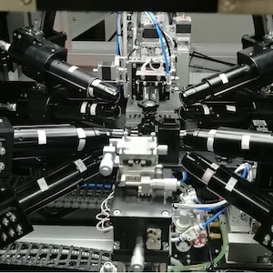
To date, there are two words that are synonymous with PTH rework: copper dissolution. Arguably, the single largest issue surfacing from the lead-free conversion in PTH rework is the highly corrosive nature of the Sn/Ag/Cu (SAC) lead-free alloys. The industry has struggled to optimize the current solder fountain rework process for successful PTH rework — obtaining adequate barrel fill while at the same time not dissolving the copper barrel wall (Figure 8). Ironically, future challenges will continue to revolve around managing the Cu dissolution and barrel fill of a connector now assembled onto a large, thermally massive product. The increase in board thickness and ground layer connections proportionally increase the difficulty of obtaining adequate barrel fill levels. In many cases, this problem may push the limitations of the current PTH rework equipment set, and new innovative platforms may need to be developed to handle this type of rework. The larger the board, the more heat is required to efficiently re-melt the solder within each barrel. Recent attempts by one equipment vendor have been to develop a modified solder fountain rework machine that will preheat the board before and continue to preheat the connector through use of topside convection during the PTH rework operation (Figure 9). This attempt to increase the core temperature of the product, as well as the connector being reworked, throughout the rework process may solve these impending rework predicaments.
 Figure 9. Topside preheat during PTH DIMM rework (ref: Air-Vac Engineering).Conclusion
Many of the problems and areas of focus over the next few years with regards to rework will be related to large, multi-layered boards making the conversion to lead-free, decreasing component sizes, and new component technologies. The solutions to these challenges will most likely consist of a combination of equipment evolution, process optimization efforts, and designing future products to better accommodate and address the challenges faced in manufacturing.
Craig Hamilton, process development consultant, Celestica, may be contacted at chamilto@celestica.com. Subscribe
Join the PennWell SMT Group on LinkedIn
Become a Fan on SMT's Facebook Page
Post your electronics manufacturing, SMT-related material to the #SMT community on Twitter. Use the #SMT hashtag.
Share on:


