


 The Knowledge Base: The Transformative Role of AI and ML
 Standard of Excellence: Collaboration—The Right Path to Innovation
 Global Sourcing Spotlight: Golf, Friedman, and the Benefits of Global Sourcing
Advances in Ionic Testing
December 31, 1969 |Estimated reading time: 10 minutes
Since the birth of the PCB, there has been a need to test for residual ionic contamination, which can lead to corrosion and dendrite growth. Whether on bare boards or finished assemblies, contamination can cause current leakage across insulating surfaces - resulting in shorts. This article explains advancements in ionic cleanliness testing, including heated dynamic ionic contamination test systems and their benefits.
By Bill Boyd, Specialty Coating Systems
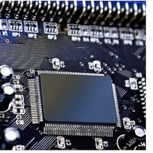
The need to test for residual ionic contamination has been around since the inception of the PCB. Ionic contamination can lead to corrosion and dendrite growth. Whether on bare boards or finished board assemblies, contamination can cause current leakage across insulating surfaces - resulting in shorts. This is particularly common in high-density, fine-pitch packages. Ionic residue contains molecules that are conductive when in solution. Some common sources of ionic residue include plating chemistries, flux activators, perspiration, ionic surfactants, and ethanolamines. Coupled with exposure to humidity in normal environments, ionic contamination can increase the speed of circuit and assembly degradation dramatically (Figure 1).
 Figure 1. Ionic contamination can increase the speed of circuit and assembly degradation in populated board assemblies in the field.
Developed in the 1970s, the resistivity of solvent extract (ROSE) test was the first available to determine ionic-contamination levels. It still is in use today, as is a modified version. This extraction technique finds ionic residues, or ions, by dissolving and extracting them in a solvent; the conductivity of this extract is then measured. IPC-TM-6502.3.25, IPC-TM-650, method 2.3.26 and 2.3.26.1, outline in detail the procedure for performing all basic ROSE testing.
Ion chromatography (IC) and surface insulation resistance (SIR) were the first in-depth testing formats, and still are in use today. IC is the most common tool for precision testing and process base lining. It has the capability to quantify and identify specific ionic species present on an electronic device. The device to be tested is placed into an ionically clean bag and immersed in an extract solution of 75% alcohol and 25% deionized water at 80°F for one hour. This is a more vigorous extraction method than those used by automated ROSE equipment; it enables a trained scientist to determine the exact source of ionic contamination. The test requires a laboratory, dedicated equipment, and highly trained personnel.
SIR testing measures the effect of contamination remaining on the board (IPC TM-650-2.6.3.3). It consists of an electrical test that measures a change in electrical current over time, and typically is performed at elevated temperatures and humidity levels. This test is intended to characterize fluxes using a standard comb pattern at 85% relative humidity (RH) and 85°F. The presence of contamination lowers the insulation resistance of the material between conductors. SIR testing can detect the presence of ionic or organic contamination, but cannot pinpoint the type of contamination, or its degree. SIR testing results only show whether the surface resistance is low. Test times range from 4 to 56 days.
IC breaks down contamination into the highest level of detail possible. SIR gives suitable answers on the surface conductivity of the board. The main drawback for both of these testing technologies is that they take special facilities to conduct the tests, and can take days or weeks to complete. As a result, they are not attractive for today’s high-mix, high-speed, and high-volume production lines - unless used as spot-check backup methods for use with faster in-line quality-control testing procedures. They are, however, valuable in R&D environments.
The need for faster test results brought about the first production-level ionic testing equipment. Initially, all testing systems used cold solutions; the first of which were static. In static testing, a solvent is deionized to a stable resistivity. The board is added to the test cell, and soluble ionic residues drive down the resistance. The change in resistivity is then used to calculate the cleanliness of the board or assembly.
Dynamic testing was developed next. This method is performed similarly to static testing, with the exception that the solution is deionized during testing, and the change in resistivity is plotted against the time it takes to deionize the solution back to the original starting resistance. Dynamic testing was more efficient, but the problem was that a cold solution pumped over a long production period rose in temperature. If the shift started at 7 a.m., and both the ambient and solution temperature began at 72°F, the friction from pumping soon would warm the solution to 90°F or 100° F. As the temperature increased, the ionic contamination was better solublized, and test results were different as the day progressed. This brought about the development of heated ionic test systems. In these designs, the solution is heated to a specific temperature, and that temperature is maintained consistently. This means that the test is always the same; therefore, results are consistent.
The modified ROSE test (IPC-TM-6502.3.25.1) is one of such heated processes. This method involves thermal extraction like the standard ROSE test, but the PCB is exposed in a solvent at a predetermined temperature for a specified time period. The ions present on the PCB are drawn into the solvent solution, and the solution is tested using an ionograph-style test unit. The results are reported as an amount of bulk ions present on the PCB per square inch.
Technology Advancements
The modified ROSE test is the basis for most modern production-level ionic test systems. Both static and dynamic systems are available, as are heated and cold test systems. There are manufacturers who swear by each type, although it has been shown that cold test solutions are not as accurate as heated temperature-controlled tests because the variability in temperature over time. Still, they can be relatively accurate for low-volume applications. The latest ionic testing systems for production-line applications have built upon, rather than changed, basic platform technologies. The modified ROSE test basics are well accepted, highly accurate, and efficient. The newest systems have added to this format, using the heat-controlled, dynamic technology within an inerted atmosphere. Both the power panel and controls are inerted.
 Figure 2. Heated dynamic testing systems circulate solution from the test cell - past a conductivity probe - through a circulation pump, a flow meter and DI columns, and then back into the test cell. Therefore, the solution is always in a cleaning process.
These heated dynamic testing systems circulate solution from the test cell, past a conductivity probe; then through a circulation pump, a flow meter, and DI columns; and finally back into the test cell. Therefore, the solution is always in a cleaning process (Figure 2). A baseline measurement is obtained by first allowing the solution to circulate in the system until the conductivity stops decreasing. When the baseline has been established, the test sample is placed into the test cell. As ions are dissolved into the solution, it is circulated past the flow meter and the conductivity probe.
Through the use of a special set of calculations, a contamination “snapshot” is taken of this section of the extract solution and the amount of NaCl is calculated and stored. The solution then goes on to the de-ionization (DI) columns.
When the solution returns to the test cell, the ions have been stripped out, leaving only new ions extracted from the test sample in the solution. These ions circulate past the flow meter and conductivity probe, and another “snapshot” is taken. The NaCl is calculated and added to the previous amount, and the solution goes back to the DI columns, back to the test cell, and so on.
Eventually, when all ions are removed from the test sample, the extract solution will consist only of cleaned-up solution, which must be returned to its baseline. The sum of all the contamination “snapshots” is then divided into the area of the test sample, and this is reported as the level of contamination present on the test sample. Because baseline has been achieved, the solution is ready for the next test.
To make the systems more production-line friendly, Bluetooth technology enables the controlling computer and monitor to be set up at a remote workstation. This remote access enables a production or quality engineer to monitor the testing process in real-time from his desk, and keeps the system footprint to a minimum.
 Figure 3. Controlling software provides enhanced graphical and database capabilities. It allows test results to be compared with previous tests.
Software is a key enhancement to the newest systems. Test results can be compared with tests that were run a day, a week, or a year ago. Any specific product data can be stored for a complete production and product history. Test results and history can be shared across a network or online (Figure 3). The most advanced systems of this type today are also ETL-approved.
 Figure 4. Ionograph/dynamic ionic testing systems software is user-configurable with multiple operating and test parameters.
To make the test procedures more cost-effective for the manufacturer, the latest heated dynamic ionic contamination test systems are also self-calibrating and easy-to-operate. A menu displays all circuit boards that are programmed into the machine. The operator chooses from the list, and the machine is ready to accept that board (Figure 4).
Another important feature for an active production environment is speed. The next-generation testing systems are designed to provide a quick and accurate answer, typically between 2-15 minutes.
Applications
There are key areas to check for ionic contamination:
- Board build: during the manufacturing of raw circuit boards, ionic testing is used at different levels during the board-building process, as required by IPC standards. The key is that when the boards arrive at the customer site, the system tests them to ensure all liquid-photo-imagable and dry-film masking cured properly, and the boards are free of ionic contamination (Figure 5).
- Incoming boards: when new stock comes into the production house, it’s imperative that circuit boards are free of contamination before being populated. To verify this, ionic testing typically should be conducted after cleaning to ensure that all flux residues have been removed.
- Production: another critical time during production is before any conformal coatings are applied to an assembly. It would defeat the purpose of building a reliable assembly if coating was applied to a populated board on top of ionic residue.
- Final test: a post-assembly test is key, and can be done by choosing a random lot per run or testing each assembly. If something does not pass final contamination inspection, and it is checked in as a clean board, then there is something askew in the assembly process, and backtracking is needed to determine where the contamination originated.
Conclusion
The benefits of the latest technology in heated dynamic ionic contamination test systems include high accuracy and speed. These systems also are effective with the latest chemistries and lead-free formulations. IC and SIR can detail contamination down to the finest level; however, modern production cannot be held up for the days or weeks it takes to obtain these results. Manufacturers do not want to send a shipment out, only to recall products because a contamination test came in positive weeks after the boards left the plant.
IC and SIR have their place. When time is not limited and detailed development of a new material, process, or board configuration is needed, these types of laboratory tests are invaluable. They also are quite effective when used in conjunction with production-line heated dynamic ionic test systems for periodic fail-safe checking, and to follow-up on problems detected by the production test system. They are very detailed, but take a substantial amount of time and resources to conduct.
 Figure 5. It is important that during the manufacture of raw circuit boards, ionic testing is used at different levels during the board-building process.
The bottom line is this - modern heated dynamic test systems will provide timely results. If there’s something wrong with incoming boards, they can be replaced by new stock quickly. If the boards fail in production, this type of equipment will show that there is something wrong in the line. Cleaning may be at fault. Perhaps the boards are being over-fluxed or subject to poor solder masking. This testing enables the manufacturer to see that there is a problem, and retrace the process to discover which step is out of control.
Cleanliness of boards and assemblies should be addressed periodically as a quality-control tool . Alterations in cleaning methods and changes in material chemistries warrant the greatest attention to cleanliness testing. If more-detailed testing is needed to find and correct a problem, highly detailed analysis can be done by sending the product to a lab for IC or SIR processing. However, the continued use of production-line IC test systems will flag any potential contamination problem first, so that IC or SIR processing can be used for detailed back-up testing. Modern heated dynamic ionic contamination test systems make this process easier to implement.
Bill Boyd, equipment program manager, Specialty Coating Systems, Inc., may be contacted at (317) 472-1248; e-mail: bboyd@scscoatings.com.
Share on:


