


 Nolan's Notes: The Next Killer App in Component Manufacturing
 The Knowledge Base: Unlocking the Invisible—The Critical Role of X-ray Technology
 Standard of Excellence: Turning Negative Customer Feedback Into Positive Outcomes


STEP 10: Rework and Repair
December 31, 1969 |Estimated reading time: 7 minutes
Quality, efficient rework influences BGA implementation success. With lead-free processes, the quality of rework becomes crucial as temperatures rise. This article focuses on heating - the biggest issue of lead-free rework - and how best to reflow array-package components on double-sided PCBs.
By Paul Wood, OK International
Over the years, circuitry and components have become smaller and more delicate, but have grown in complexity and functionality. At the same time, fierce competition has put pressure on every aspect of the manufacturing cycle; throughput and profitability are key. Against this backdrop, rework - far from being an optional or occasional task - has become unavoidable. It is also one of the riskiest, most demanding parts of the electronics cycle, especially where array packages are involved. Quality, efficient rework is the most important factor influencing successful, profitable BGA implementation. With the introduction of lead-free processes, the quality of rework becomes more crucial, as lead-free materials call for higher processing temperatures that may stress or cause irreversible damage to heat-sensitive board materials and components.
Whether using lead-bearing or lead-free processes, and whether reworking conventional or array-package components, the principal steps in rework (desoldering, removal, site cleaning, and reattachment) remain the same. Because these are well documented and understood by rework professionals, this article focuses on heating - the biggest issue introduced by lead-free rework - and how best to reflow array-package components on large, double-sided PCBs.
Leaded solder melts at 183ºC, and reflows at 210-220°C; tin/silver/copper (SAC) lead-free solder alloy melts at 217°C, and reflows between 235°C and 250°C. This is very close to the temperature at which components will be damaged. The IPC limit for components at 260ºC, for example, is already too high for some component manufacturers. It is clear that processing windows are tighter than ever before. It also is clear that temperature profiles such as target temperature levels, ramp speeds, soak times, delta temperatures, and heater size and positioning must be precisely established and controlled if faults are to be avoided. Higher temperatures are necessary; to create a reliable joint, lead-free solder must be heated to at least 230ºC. As process variations are in the order of ±5ºC, it follows that the lowest temperature to achieve a reliable solder joint ranges in 235º-245°C, according to iNEMI standards.
BGA Lid Damage
When working at these temperatures, one of the biggest challenges is maintaining a low temperature on the reworked BGA lid, which is often made of a heat-sensitive plastic. In large BGAs, high temperatures will cause the lids to warp down in the corners, a major cause of bridging, especially with a component that is difficult to solder correctly. This can be due to the use of poor BGA substrate materials. Some component manufacturers have not redeveloped their original lead-processing packages for lead-free temperatures, but have simply balled them with lead-free solder, or perhaps they are offering a less-expensive, transitional package as they move to lead-free.
Another factor to consider when reworking is the ΔT, or temperature difference between various parts of the assembly. A good rework process, with tight process control, will ensure that the difference in temperature between the solder balls being reworked is close to 5ºC, and under 10ºC. Similarly, to avoid board warpage and subsequent reliability problems, some manufacturers specify a ΔT of 7ºC vertically through the PCB at the rework site.
Ramp Speed
Time is money; and the faster the throughput, the better the profit margin. This is as true for rework as it is for any other portion of the manufacturing cycle. Therefore, the faster reflow is achieved, the better. Accordingly, rework professionals are under pressure to keep temperature ramp rates high for lead-free solders, also partly because of the higher target temperatures. Ramp-down is also faster, ensuring that the time spent over melt and peak temperatures remains as short as possible. Process control is key here.
Heaters and Air Temperature
When heating array-package components, convection heaters, which use hot air forced through a nozzle, are more practical than conduction heaters, as they have an immediate effect, yet they allow temperatures to ramp gradually throughout the assembly and package.
A factor of major importance is the size and position of the heaters relative to the PCB. If heat is concentrated only on the area to be reworked, the substrate will reach temperatures that are far in excess of what can be tolerated while the rest of the PCB remains cool. This will cause the PCB to warp, stressing its interconnections; high local temperatures can blister the solder resist.
To avoid these problems, the standard approach to heating lead-process PCBs involves heating not just the target BGA, but the entire board, to reflow temperatures, by setting air temperature to a maximum of 220°C. In this way, component surface temperatures may reach 190º-200ºC, while solder heats to 220ºC.
 Figure 2. By keeping the rest of the PCB cool relative to the rework site, the risk of heat damage is eliminated, and the site can be cooled quickly after reflow.
Unfortunately, for several reasons, some companies have discovered that the same approach cannot be used for lead-free PCBs because higher air temperatures would be disastrous, especially for the underside of the board. This is because, like the topside, it is populated with delicate components and connectors. Their plastic parts can warp and deform - necessitating additional rework - or their leads can reflow only partially. Components and connectors then may elongate, sag, stretch the joints, or drop off the underside of the board. Because such a potential exists for defects and damage, these components - like those on the topside - should be checked for burning, discoloring, or warping after rework.
Some rework professionals will try to avoid these risks by pre-heating their lead-free boards from underneath to below the 217ºC melting point, and then heating the BGA directly from above until reflow is achieved. Although this is better than no pre-heat at all, the BGA will nevertheless be exposed to temperatures over its tolerance limit to get its underlying solder balls to reflow - incurring the risk of heat damage.
The Ideal Profile
Taking these issues into consideration, it becomes clear that array-package rework on large, double-sided PCBs requires thermal profiles that are programmed and controlled continuously. These should be used on reflow equipment that is large enough to house and support the PCB to protect it from warpage, powerful enough to pre-heat the entire board quickly, and accurate enough to reflow only the part that is to be reworked, within precise time and temperature limits (Figure 1).
 Figure 1. An ideal profile for safe, controlled BGA rework on a double-sided PCB is shown. The board is preheated to 190°-200ºC, then focused heaters take the rework site to precise reflow temperatures for the minimum time needed for optimum rework.
Naturally, the ideal thermal profile for any given board will depend on its size, mass, component types, and component density. For a large, double-sided PCB with array-package components, for example, this includes a pre-heat stage using a large array heater positioned below the board to heat the entire assembly to a temperature below the solder melt-point, ideally 190ºC. At this point, the large underside heater is switched off and is replaced with topside and underside heat nozzles that are concentrated locally on the BGA rework site to take it to reflow temperature for a brief period of time. Because the pre-heat stage works in tandem with local heat nozzles, the nozzles can use lower-temperature airflow to achieve target temperatures. This reduces the risk of heat damage to the BGA and its lid, as well as the surrounding soldermask.
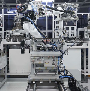
 Figure 3. Array-package rework system.
Keeping the rest of the PCB at 190-200ºC means rework site temperature can be ramped back to safe levels quickly, eliminating the risk of local warpage on the board. Because the rest of the board remains below melt temperatures, there is less risk of damage to underside devices, and solder reflows only where necessary. It is also possible to keep ΔT across the board within tight tolerances.
Conclusion
Experience, patience, and trial-and-error have gone into developing an outline of a rework heat process for double-sided boards that serves as a basis for developing optimal product-specific thermal profiles. Precision and speed is key to successful rework; it is not always enough to simply turn up the temperature on existing hardware. It is essential that rework equipment is powerful enough to work accurately at the higher temperatures needed for lead-free processes, while closed-loop feedback and dedicated control software are becoming key to quality array-package rework.
Paul Wood, market development manager, OK International, may be contacted at (714) 779-9910; e-mail: pwood@okinternational.com.
Share on:


