


 Powering the Future: Why True Ceramic Circuits Are Not Just ‘Better PCBs’
 Global Sourcing Spotlight: The Global Quality Gap—Why Consistency Wins the Contract
 Knocking Down the Bone Pile: Precision Milling of Underfilled SMT Components


The desire for higher throughput and better integration of SMD lines require new technological solutions. In line with this, Rehm Thermal Systems has introduced a vacuum unit that enables convection soldering processes with or without vacuum – with only one soldering system.
Energy-efficient, low-maintenance and voidless, the new solution features two technologies—the convection reflow soldering system VisionXP+ and a vacuum chamber—that had been united to provide this new option.
As soon as the solder is molten—and while the solder is still in the optimum molten state—the VisionXP+ with vacuum option reliably removes voids and gas emissions. Void content of less than 2% can be realised with a vacuum between 100 mbar and 10 mbar (Figure 1a). For an exact setting of the process parameters the vacuum level is measured directly in the process chamber. Pressure gradient and the speed of the vacuum process can be set individually and profile parameters can be saved. The mechanical system construction allows to optionally use the vacuum or to apply it as a classic convection soldering system (Figure 1b).
Figure 1: X-ray images of a QFN44 solder joint following soldering process (a) with vacuum and (b) without vacuum with the VisionXP+ Vac system.
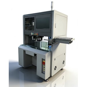
The vacuum chamber is installed (Figure 2) as an enhancement to the available peak zones. The integrated pyrolysis and separate filtering of the atmosphere extracted from the vacuum chamber makes maintenance and cleaning easy. The vertical travel range and automatic service positions of the vacuum chamber allowing good access to the internal mechanisms during maintenance periods and minimises downtimes and reduces maintenance effort.
Figure 2: A convection soldering system of type VisionXP+ Vac with vacuum chamber.
The system has a higher throughput by a second transport track and comes with a tripartite transport system: pre-heating/peak area, vacuum unit and cooling zone, and optional with a central support for particularly wide boards. Transportation speed in the cooling zone can be reduced, and cooling time of components can be extended to assure optimum temperature for the subsequent process steps.
All heating zones are regulated individually and thermally separated from each other to assure a stable reflow process, flexible pressure and temperature profile guidance. Figure 3 shows a temperature profile with the vacuum process switched on. With a very low vacuum of 10 mbar profile settings ≤3K/s heating, tL≤90s, TP≤240°C had been fulfilled. With the integrated heating in the chamber, the component temperature can be adapted to the most common standards.
Figure 3: Pressure and temperature profile of a soldering process with the VisionXP+ Vac.
In order to identify a suitable combination of condensation or convection soldering and vacuum technology, the individual aims should be analysed. Table 1 compares several important features of the two vacuum soldering procedures.
Table 1: Comparison convection and condensation soldering systems with vacuum.


