


 Global PCB Connections: Rigid-flex and Flexible PCBs—The Backbone of Modern Electronics
 Flexible Thinking: The Key to a Successful Flex Circuit Design Transfer
 Happy’s Tech Talk #29: Bend-to-Install Semi-flex FR-4


Flex Circuit Shielding Design Options
October 22, 2015 | Mike Morando, PFC Flexible CircuitsEstimated reading time: 4 minutes
Figure 3: Silver paste screened over a coverlay showing the via stitches down to a ground line—another coverlay goes on top to protect the silver.
- EMI Thermoplastic Shielding film—latest technique. This technology is the newest and most flexible shielding technique. The ultra-thin, ultra-flexible materials were developed for the cell phone market. The manufacturing process has been dramatically improved, making it only slightly more expensive than the older technologies. North American flex shops who use this material are pushing their customers in this direction. It is the thinnest and most flexible. It is easy to apply and creates a 360 degree shield similar to a silver paste or stitched copper via.
Figure 4: Material stack of the thermoplastic shielding film.
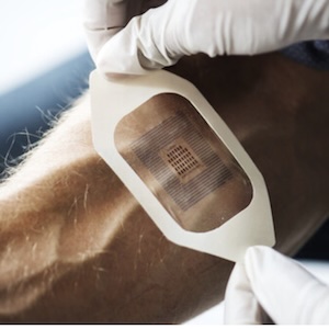
Figure 5: Thermoplastic shielding film applied to circuits. Easy for your vendor to apply, but material is still expensive.
Shielding—Design for Manufacturing—a Review of what we learned
Most of the North American flex suppliers can provide all four solutions mentioned below, but they will steer you to the technique they are most comfortable with. The most important design decisions for shielding flex circuits are flexibility/bendability and cost.
Here are my impressions:
- Adding layers of copper to shield, while adding potentially excellent shielding characteristics, adds cost, weight and thickness, and can prove to be a disaster when trying to bend the circuit. This method requires via stitching to prevent “leakage.”
- Adding cross-hatch layers can provide excellent shielding characteristics again, but still adding layers, weight, and will affect flexibility. This also requires via stitching to prevent “leakage.”
- Conductive paste allows better flexibility and lighter weight, and better coverage of shielding. Requires via stitching.
- Thermoplastic shielding film is slick stuff. Easy to apply, thin, light, and bendable. It allows no side leakage. It was originally made for cellphones so the material has been proven, but is more expensive (by 25%) than shielding with normal/older techniques.
Mike Morando is VP of sales and marketing for PFC Flexible Circuits Limited.
Page 2 of 2Share on:


Testimonial
"In a year when every marketing dollar mattered, I chose to keep I-Connect007 in our 2025 plan. Their commitment to high-quality, insightful content aligns with Koh Young’s values and helps readers navigate a changing industry. "
Brent Fischthal - Koh YoungSuggested Items
Episode 6 of Ultra HDI Podcast Series Explores Copper-filled Microvias in Advanced PCB Design and Fabrication
10/15/2025 | I-Connect007I-Connect007 has released Episode 6 of its acclaimed On the Line with... American Standard Circuits: Ultra High Density Interconnect (UHDI) podcast series. In this episode, “Copper Filling of Vias,” host Nolan Johnson once again welcomes John Johnson, Director of Quality and Advanced Technology at American Standard Circuits, for a deep dive into the pros and cons of copper plating microvias—from both the fabricator’s and designer’s perspectives.
Nolan’s Notes: Tariffs, Technologies, and Optimization
10/01/2025 | Nolan Johnson -- Column: Nolan's NotesLast month, SMT007 Magazine spotlighted India, and boy, did we pick a good time to do so. Tariff and trade news involving India was breaking like a storm surge. The U.S. tariffs shifted India from one of the most favorable trade agreements to the least favorable. Electronics continue to be exempt for the time being, but lest you think that we’re free and clear because we manufacture electronics, steel and aluminum are specifically called out at the 50% tariff levels.
MacDermid Alpha & Graphic PLC Lead UK’s First Horizontal Electroless Copper Installation
09/30/2025 | MacDermid Alpha & Graphic PLCMacDermid Alpha Electronics Solutions, a leading supplier of integrated materials and chemistries to the electronics industry, is proud to support Graphic PLC, a Somacis company, with the installation of the first horizontal electroless copper metallization process in the UK.
Electrodeposited Copper Foils Market to Grow by $11.7 Billion Over 2025-2032
09/18/2025 | Globe NewswireThe global electrodeposited copper foils market is poised for dynamic growth, driven by the rising adoption in advanced electronics and renewable energy storage solutions.
MacDermid Alpha Showcases Advanced Interconnect Solutions at PCIM Asia 2025
09/18/2025 | MacDermid Alpha Electronics SolutionsMacDermid Alpha Electronic Solutions, a global leader in materials for power electronics and semiconductor assembly, will showcase its latest interconnect innovations in electronic interconnect materials at PCIM Asia 2025, held from September 24 to 26 at the Shanghai New International Expo Centre, Booth N5-E30