


 Dan’s Biz Bookshelf: Four Important Books You Need to Read (Not Just Say You Have)
 The Marketing Minute: Cracking the Code of Technical Marketing


Biochip Offers Leukocyte Counting for HIV Diagnosis
March 15, 2016 | University of Illinois College of EngineeringEstimated reading time: 2 minutes
Researchers from the University of Illinois at Urbana-Champaign have developed a highly sensitive biosensor based on a differential immuno-capture technology that can detect sub-populations of white blood cells. As part of a small, disposable biochip, the microfluidic biosensor can count CD4+/CD8+ T cells quickly and accurately for AIDS diagnosis in the field. This is a follow-up of the work earlier published by the group in Science Translational Medicine.
"There are 34 million people infected with HIV/AIDS worldwide, many in places that lack testing facilities," explained Rashid Bashir, an Abel Bliss Professor of Engineering and head of the Department of Bioengineering at Illinois.
"An important diagnostic biomarker for HIV/AIDS is the absolute count of the CD4+ and CD8+ T lymphocytes in the whole blood. The current diagnostic tool--a flow cytometer--is expensive, requires large blood volume, and a trained technician to operate," Bashir said. "We have developed a microfluidic biosensor based on a differential immuno-capture electrical cell counting technology to enumerate specific cells in 20 minutes using 10 microliters of blood." (There are about 50 microliters in a drop of blood).
Human blood is composed of 45 percent of cells with 5 million erythrocytes as compared to only 7000 leukocytes in one microliter of blood. Specific leukocytes like CD4 T cells are of the order of 50-1000 cells per microliter. Electrical cell counting can differentiate cells based on size and membrane properties depending on the frequency of the interrogation signal. However, differentiating cells of same morphology is a challenge.
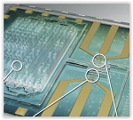
Differential immuno-capture biochip schematic: 1. Ten microliters of blood is infused into the biochip. 2. Erythrocytes were lysed and the leukocytes were preserved using as custom-made lysing and quenching buffers get mixed with blood. 3. The leukocytes pass over co-planar platinum microfabricated electrodes and are counted. 4. Specific cell antibodies e.g. monoclonal CD4 T cell antibody is initially adsorbed on the capture chamber. CD4 T cells get captured as they interact with the antibodies in the chamber. 5. Remaining leukocytes gets counted again with second counter. The difference in the respective cell counts give the concentration of the cells captured.
Page 1 of 2
Share on:


Testimonial
"Advertising in PCB007 Magazine has been a great way to showcase our bare board testers to the right audience. The I-Connect007 team makes the process smooth and professional. We’re proud to be featured in such a trusted publication."
Klaus Koziol - atgSuggested Items
Zuken Launches CR-8000 2025 with AI-Enhanced Support for High-Speed, High-Density PCB Design
05/21/2025 | ZukenZuken, a global leader in electronic design automation (EDA) solutions, has announced the release of the 2025 updates to its flagship PCB design applications, CR-8000 Design Gateway and Design Force.
RF PCB Design Tips and Tricks
05/08/2025 | Cherie Litson, EPTAC MIT CID/CID+There are many great books, videos, and information online about designing PCBs for RF circuits. A few of my favorite RF sources are Hans Rosenberg, Stephen Chavez, and Rick Hartley, but there are many more. These PCB design engineers have a very good perspective on what it takes to take an RF design from schematic concept to PCB layout.
IPC Announces New Training Course: PCB Design for Military & Aerospace Applications
12/23/2024 | IPCIPC announced the launch of a new training course: PCB Design for Military & Aerospace Applications.
eCADSTAR Sets New Standards for Compact PCB Design with Etched Inductor Parts
06/12/2024 | ZukenZuken announces the 2024 release of eCADSTAR, Zuken’s next-generation PCB design system for small and medium businesses. The new release includes a number of improvements ranging from enhanced design reuse, simplified revision tracking and more robust schematic design.
Elementary, Mr. Watson: Ensuring Design Integrity
03/28/2024 | John Watson -- Column: Elementary, Mr. WatsonBack in February, many of us watched the "Big Game." It reminded me of the saying, “It's not how you start that is important, but rather how you finish." It is perfectly okay when you are talking about sports, you get off to a bad first half and need to recover in the second half. However, when it comes to PCB design, this is not a good practice. If things start badly, they usually don't recover. They continue down that same path, costing more money and losing design time.