-

- News
- Books
Featured Books
- smt007 Magazine
Latest Issues
Current Issue
Do You Have X-ray Vision?
Has X-ray’s time finally come in electronics manufacturing? Join us in this issue of SMT007 Magazine, where we answer this question and others to bring more efficiency to your bottom line.

IPC APEX EXPO 2025: A Preview
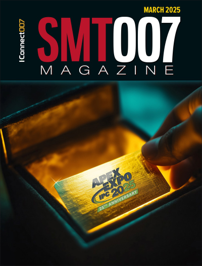
It’s that time again. If you’re going to Anaheim for IPC APEX EXPO 2025, we’ll see you there. In the meantime, consider this issue of SMT007 Magazine to be your golden ticket to planning the show.

Technical Resources
Key industry organizations–all with knowledge sharing as a part of their mission–share their technical repositories in this issue of SMT007 Magazine. Where can you find information critical to your work? Odds are, right here.
- Articles
- Columns
Search Console
- Links
- Media kit
||| MENU - smt007 Magazine
Cleaning under Low-standoff Components
December 31, 1969 |Estimated reading time: 7 minutes
BY Umut Tosun, M.S. Chem. Eng., Zestron and Dirk Ellis, Speedline Technologies
The presence of miniaturized chips, combined with other geometric obstacles, has affected cleaning. As these challenges emerge, users must determine that residues are removable by the cleaning agent of choice then address the geometric challenge. Worst-case conditions and best-case scenarios both figure into this study.
The emergence of smaller components is becoming a significant challenge to the cleaning process. With gaps as little as 1 mil, contaminant removal under and around chip components presents the greatest problem. The cleaning community has taken particular notice of the latest chip packages, such as 0201s and 01005s, and related geometric obstacles. To address these issues, users first must determine that residues are removable by the cleaning agent of choice before attacking the geometric challenges. Worst-case conditions were used to ensure validity and relevance over time. Best-case scenarios are referenced as benchmarks.
Initial cleanability was confirmed for tested residues and given standoffs. Component types 0603 and 0805 were chosen with standoff heights less than 1 mil. The initial test series helped determine best- and worst-case parameters, which in turn provided the basis for all subsequent phases. Results were evaluated by three different chemical engineers to establish repeatability.
Wash temperature and belt speed settings were adjusted during the testing period. A spray-in-air conveyorized inline cleaner provided efficient mechanical agitation. Two spray manifold apparatuses - one with four spray manifolds each having nine V-Jet nozzles and the other with 16 spray manifolds each having 19 JIC solid-stream nozzles - were used. Soldering was performed in a 10-stage reflow oven under air atmosphere. Reflow under nitrogen demonstrates significantly better cleaning results; the authors therefore opted for reflow with air to resemble worst-case scenarios.
Findings Phase 1
The initial results for lead-free paste formulations demonstrated that the standoff height created a difficult initial challenge to overcome. Tests were started at 10% cleaning solution concentration, then temperature and belt speed were adjusted incrementally. None of the results showed fully cleaned substrates. The experiments were conducted at a higher operating concentration to address surface tension considerations. At 150°F (65.5°C), higher concentrations of the cleaning agent and slower belt speed did not change outcomes. Time delays after reflow were addressed as well; cleaning immediately after reflow left residues. Increasing the temperature to 160°F (71.1°C) provided satisfactory results at a belt speed of 0.6 feet/min. Increasing the time delay after reflow from 2 to 20 hours confirmed positive findings.
This iterative set of experiments also was conducted for leaded formulations. Again a 10% solution was the starting point, using 150°F and 3.5 feet/min., which turned out negative. At 1 foot/min., the flux residues were only partially cleaned. Variations of delay after reflow made little to no difference. The process parameters were slightly adjusted to lower the belt speed, which improved cleaning results significantly. A concentration increase to 15% did not improve cleaning results. This confirms that cleaning agent surface tension for low-standoff cleaning trials is not the only physical variable to consider. A final belt speed of 0.6 feet/min. at 160°F and 10% concentration provided satisfactory results. Results of the lead-free and leaded testing are illustrated in Figures 1A and B, respectively.
Phase 2
Having established the overall best process parameters during phase 1, the authors now wanted to determine the impact of increased component density. Using the lead-free formulation, the process parameters were 15%, 160°F, and 0.6 feet/min. The component density for 0603s and 0805s then was increased to 18, 24, and 30, respectively. All results were found to be 100% clean. Switching to leaded formulations further confirmed the cleaning trend. Worst-case conditions with 30 components (0603 and 0805) in a row formation were cleanable using 10% cleaning solution concentration, 160°F, and 0.6 feet/min. A time delay after reflow of up to 22 hours made no difference. Fewer components (18 and 24) also showed positive results with the same settings. Partially cleaned results were found with higher belt speeds.
 Figures 1A & B. Results of removing contaminants under low-standoff components soldered with leaded and lead-free paste, phase 1.
null
Phase 3
The authors designed experiments to further increase mechanical energies and improve throughput. All previous tests had been conducted with the four-spray-bar manifold (Figure 2A). Each spray bar is equipped with nine V-Jet nozzles distanced 2˝ apart from each other. In this tertiary phase, the number of spray bars increased by a factor of four to sixteen (Figure 2B).
After confirming successful cleanliness results, the authors used more demanding process parameters for lead-free solder. Concentrations of 15% combined with 150°F operating temperature and 1 foot/min. speed did not provide 100% cleanliness. An increase in temperature to 160°F still left white residues under both component sizes. Overall, the belt speed could not be increased to 1 foot/min. even with 16 spray bars. However, the concentration could be lowered by 5%.
 Figures 2A & B. Four spray bars versus sixteen spray bars in the cleaning section.
Unlike lead-free, the leaded formulation enabled higher belt speeds - up to 1.2 feet/min. This particular result was obtained with a time delay after reflow of 2 weeks. Immediate cleaning after reflow, however, did not allow for belt speeds above 1.2 feet/min. Partially cleaned results were found at 1.5 and 1.7 feet/min.
Phase 4
To simulate lower spray volumes and pressures, the number of spray arms subsequently was reduced to four and spray pressures of 70 and 50 psi were used. Starting at 70 psi and 0.6-feet/min. belt speed, 15% cleaning solution concentration and 160°F, the cleaning process failed to provide good results with lead-free formulations. Lower pressure did not improve findings. Somewhat better results were found with eutectic solder, but slight residues remained under the components at all times.
Overall best results for a lowered spray volume were found for leaded pastes again. Spray pressures of 70 psi were able to clean at 1 foot/min., 15% concentration, and 160°F. A reduction to 50 psi also demonstrated positive results under the same conditions. Attempts to decrease the concentration to 10% were unsuccessful. As a final data point, best-case scenarios were established through use of an easily removable flux residue. Belt speeds ranged from 1.7 to 2.1 feet/min. using 10% concentration at 140°-150°F (60°-65.5°C), respectively. Spray pressures included 70 and 100 psi.
Conclusion
With the emergence of geometries that prove harder to clean, the industry must adapt to new challenges. This study highlights current cleaning challenges addressed through various means. Cleaning technology providers have to continue following and anticipating the industry’s evolving needs, on the cleaning agent and cleaning equipment sides. We have witnessed, for example, that a large process window was obtained where pressures and flows were the highest. Given this data, innovations should aim to further increase the cleaning process window. On the same token, new cleaning agents should be developed to facilitate penetration under low-standoff components, dealing with surface-tension issues encountered in these tiny spaces.
Umut Tosun, M.S. Chem. Eng., accredited cleaning expert and application technology manager, Zestron, may be contacted at u.tosun@zestronusa.com. Dirk Ellis, product manager, Speedline, may be contacted at dellis@speedlinetech.com.
The Lead-free Perspective: High Reliability
Making the transition from lead-bearing to lead-free assembly affects every step in the process, and every material, beyond simply switching out tin/lead solder paste for a lead-free alloy. The book Lead-free Electronics: iNEMI Projects Lead to Successful Manufacturing discusses testing of various cleaning setups - changing equipment, chemistries, concentrations - to compare methods to clean lead-free PCBS. Ionic contamination (IC) testing assessed cleaning’s effectiveness on no-clean flux residues.
As stated in iNEMI’s book, “cleaning efficiency is a calculation relating the results from uncleaned boards to those of cleaned boards. Lower ionic contamination levels indicate improved cleaning.” Cleaning efficiency (CE) is expressed mathematically as

When CE = 1, cleaning had no effect on the PCB’s cleanliness. A CE value above 1 indicates cleaning improved cleanliness; a CE value below 1 shows that cleaning actually had the opposite effect - it made the PCB less clean.
The higher reflow temperatures required by lead-free alloys generate more charred no-clean flux residues, lowering cleaning’s effectiveness overall. Every cleaning situation tested showed tin/lead PCBs emerging with higher CE values than their lead-free counterparts. However, some chemistries and cleaning methods fared better with lead-free, and proved satisfactory. Higher reflow temperatures, higher tin activity, and increased flux chemistry complexity with lead-free all lead to more difficult cleaning.
Evaluation of cleaning processes found that the most efficient process for tin/lead PCBs may not translate as the best choice for lead-free. The study indicates that cleaning process does not impact CE as much as chemistry. Indeed, process efficiency “may be affected by the cleaner concentration and cleaning time factors.” Higher cleaner concentrations were linked to higher CE. Complete test data, including rankings of chemistries and equipment types, are included in “Lead-free Solder Paste Technology” in Lead-free Electronics.
This information is summarized from iNEMI’s publication, Lead-free Electronics: iNEMI Projects Lead to Successful Manufacturing, which is responsible for accuracy of data and results. The publication is edited by Edwin Bradley, Carol A. Handwerker, Jasbir Bath, Richard D. Parker, and Ronald W. Gedney; IEEE Press, 2007. The book is available through the Wiley-IEEE Press, www.wiley.com, and other international online booksellers.


