


 Knocking Down the Bone Pile: Revamp Your Components with BGA Reballing
 Global Sourcing Spotlight: Balancing Speed and Flexibility Without Sacrificing Control
 SMT Perspectives & Prospects: Artificial Intelligence Part 6: Data Module 1


Acceptance Testing Of Low-Ag Reflow Solder Alloys (Part 2)
August 13, 2015 | K. Troxel, A. Allen, E.E. Benedetto, R. Joshi, Hewlett-Packard Co.Estimated reading time: 7 minutes
In Part 2 of this two-part article series, the authors discussed the test results for low-silver alloys using these solder paste alloy assessment protocols for BGAs and leaded components, and the impact of the alloys on printed circuit assembly process windows.
Test Results and Discussion
Manufacturing DoE Results
IMC Thickness
Measured on BGA Manufacturing DoE Test Boards (see Figure 1 in Part 1) that were reflowed 3 times with a peak reflow temperature of 250 °C and 120 seconds TAL.
Two BGA body sizes were evaluated [14 mm and 23 mm]. IMC thicknesses for alloys A and B were normally distributed with no significant difference between the large and small BGA. For alloys C and D, greater variability in the large BGA IMC thickness resulted in values significantly different than smaller BGA (as seen in Figure 1 and Table 1).
Figure 1: IMC thickness distribution by Alloy (A-D) and BGA size (large/small)
Table 1: Summary of IMC thicknesses (microns)
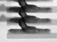
Copper Dissolution
This was measured on the BGA Manufacturing DoE Test Boards (see Figure 1 in Part 1) that were reflowed 3 times with a peak reflow temperature of 250°C and 120 seconds TAL.
Cu thickness measurements were made at each solder joint, in the middle of the joint and underneath the soldermask adjacent to the joint. Cu removed was the difference in copper thickness at these two locations. Cu dissolved was determined by subtracting Epsilon (thickness of Cu removed during soldermask etch in the PCB fab process) from the Cu removed values.
Figure 2: Cu dissolution distribution by alloy
Table 2: Summary of Cu dissolved (microns)
The amount of Cu dissolved after soldering was less for the low silver alloys than that for SAC305. The Cu dissolution results were normally distributed for the evaluated alloys but varied with alloy and BGA size (as seen in Figure 2 and Table 2). The Cu dissolution performance varied by BGA size, though not in a consistent fashion. While alloy B showed comparable Cu dissolved values between the 2 BGA sizes, alloy C and D both had more Cu dissolved for the larger BGA while alloy A had greater Cu dissolution values for the small BGA (this could be attributable to bare board Cu characteristics between the different vendors).
Page 1 of 3
Share on:


Testimonial
"In a year when every marketing dollar mattered, I chose to keep I-Connect007 in our 2025 plan. Their commitment to high-quality, insightful content aligns with Koh Young’s values and helps readers navigate a changing industry. "
Brent Fischthal - Koh YoungSuggested Items
Indium Experts to Deliver Technical Presentations at SMTA International
10/14/2025 | Indium CorporationAs one of the leading materials providers to the power electronics assembly industry, Indium Corporation experts will share their technical insight on a wide range of innovative solder solutions at SMTA International (SMTAI), to be held October 19-23 in Rosemont, Illinois.
Knocking Down the Bone Pile: Revamp Your Components with BGA Reballing
10/14/2025 | Nash Bell -- Column: Knocking Down the Bone PileBall grid array (BGA) components evolved from pin grid array (PGA) devices, carrying over many of the same electrical benefits while introducing a more compact and efficient interconnect format. Instead of discrete leads, BGAs rely on solder balls on the underside of the package to connect to the PCB. In some advanced designs, solder balls are on both the PCB and the BGA package. In stacked configurations, such as package-on-package (PoP), these solder balls also interconnect multiple packages, enabling higher functionality in a smaller footprint.
Indium to Showcase High-Reliability Solder and Flux-Cored Wire Solutions at SMTA International
10/09/2025 | Indium CorporationAs one of the leading materials providers in the electronics industry, Indium Corporation® will feature its innovative, high-reliability solder and flux-cored wire products at SMTA International (SMTAI), to be held October 19-23 in Rosemont, Illinois.
‘Create your Connections’ – Rehm at productronica 2025 in Munich
10/08/2025 | Rehm Thermal SystemsThe electronics industry is undergoing dynamic transformation: smart production lines, sustainability, artificial intelligence, and sensor technologies dominate current discussions.
Amplifying Innovation: New Podcast Series Spotlights Electronics Industry Leaders
10/08/2025 | I-Connect007In the debut episode, “Building Reliability: KOKI’s Approach to Solder Joint Challenges,” host Marcy LaRont speaks with Shantanu Joshi, Head of Customer Solutions and Operational Excellence at KOKI Solder America. They explore how advanced materials, such as crack-free fluxes and zero-flux-residue solder pastes, are addressing issues like voiding, heat dissipation, and solder joint reliability in demanding applications, where failure can result in costly repairs or even catastrophic loss.