


 Global Citizenship: Together for a Perfect PCB Solution
 Smart Automation: Odd-form Assembly—Dedicated Insertion Equipment Matters
 Nolan’s Notes: Everyone Has Their Eye on India


Bumping of QFNs/LGAs and Other Leadless Devices for More Consistent Rework
August 9, 2016 | Bob Wettermann, BEST Inc.Estimated reading time: 2 minutes

The Challenge
Leadless devices are now the greatest package style by volume (Yole Development Market Survey) being placed by electronics assemblers worldwide. These packages, due to a variety of factors, are challenging to rework. Among the greatest challenges this package presents are the solder voiding primarily on the ground plane, the inability to clean underneath the devices post rework, and the difficulty in getting similar standoff heights on both the IO and center ground. These challenges along with their increasing complexity and ever smaller package sizes challenge even the most skilled rework technicians.
In addition to the above rework challenges, the package style itself remains very difficult to inspect post reflow for a variety of reasons. As there are rarely any visible solder joints due to in most instances a lack of a solderable sidewall on the IO pads of the device, as well as the very low standoff distances between the bottom of the device and the PCB, there is very little visual inspection which can occur. This means that the reliance on a skilled x-ray technician as well as a capable x-ray system is in order.
Types of Rework Methods Available
Of the various methods for reworking leadless devices, the bumping method (Figure 1), when appropriate for the board and part at hand, is the process with the greatest first pass yield, the one with the greatest standoff distance for cleaning flux residue from underneath the device and the one with the greatest assurance of minimizing voiding.
Figure 1: Bumped leadless device prior to placement.
"Bumped" 2 x 2mm QFN Package, 0.5mm pitch, 0.2mm Wide Pads
There are numerous methods being used to rework leadless devices; either guided by the older IPC 7711 5.4.1 process guidelines or by the newest stenciling techniques. The older of these methods includes solder paste printing on the site location of the PCB followed by the placement and reflow of the device. The newer methods including IPC 7711 procedures 5.8.1.1 and 5.8.1.2 includes the device pads being “bumped” followed by their placement. The device, post “bumping”, can be placed using a rework system using paste flux or with a properly-designed “capture” stencil which has apertures that can locate and capture the “bumps” on the PCB.
Both of these latter methods for reworking leadless devices were popularized using polyimide stencils. In these methods, a polyimide stencil is placed over the land patterns on the bottom of the device. Solder paste is then squeegeed in to the apertures. The device is then reflowed. Post reflow, the stencil is peeled off leaving “bumps” on the bottom of the device (mini metal stencils can also be used when appropriate). Because the reflow is done in air, the flux volatiles can escape, thereby having the “bumped” part nearly free of voids. In addition, these stencils are thicker than the initial manufacturing stencils meaning that the final standoff height is greater when compared to traditional printing and placement. This bumping technique also greatly simplifies placement of the leadless device as a lower-skilled technician or even first-timer, when following the instructions properly, can produce the “bumps” for placement.
To read this entire article, which appeared in the August 2016 issue of SMT Magazine, click here.
Share on:


Testimonial
"Our marketing partnership with I-Connect007 is already delivering. Just a day after our press release went live, we received a direct inquiry about our updated products!"
Rachael Temple - AlltematedSuggested Items
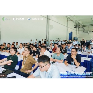
Koh Young, Fuji, and Kurtz ERSA Drive Smart Manufacturing Solutions for EV and Automotive Electronics at Kunshan, China Technical Seminar
09/11/2025 | Koh YoungKoh Young Technology, the global leader in True 3D measurement-based inspection solutions, partnered with Fuji Corporation and Kurtz ERSA to host an exclusive technical seminar for leading automotive manufacturers in East China. Held on September 4 at Fuji’s factory in Kunshan, the event gathered participants representing over 35 companies.
MacDermid Alpha Presents at SMTA New Delhi, Bangalore Chapter, on Flux–OSP Interaction
09/09/2025 | MacDermid Alpha Electronics SolutionsMacDermid Alpha contributes technical insights on OSP solderability at the Bangalore Chapter, SMTA reinforcing commitment to knowledge-sharing and industry collaboration.
Electra’s ElectraJet EMJ110 Inkjet Soldermask Now in Black & Blue at Sunrise Electronics
09/08/2025 | Electra Polymers LtdFollowing the successful deployment of Electra’s Green EMJ110 Inkjet Soldermask on KLA’s Orbotech Neos™ platform at Sunrise Electronics in Elk Grove Village, Illinois, production has now moved beyond green.
Absolute EMS: The Science of the Perfect Solder Joint
09/05/2025 | Absolute EMS, Inc.Absolute EMS, Inc., a six-time award-winning provider of fast turnaround, turnkey contract electronic manufacturing services (EMS), is drawing attention to the critical role of 3D Solder Paste Inspection (SPI) in ensuring the reliability of both FLEX and rigid printed circuit board assemblies (PCBAs).
Indium Corporation to Highlight High-Reliability Solder Solutions at SMTA Guadalajara Expo
09/04/2025 | Indium CorporationIndium Corporation, a leading materials refiner, smelter, manufacturer, and supplier to the global electronics, semiconductor, thin-film, and thermal management markets, will feature a range of innovative, high-reliability solder products for printed circuit board assembly (PCBA) at the SMTA Guadalajara Expo and Tech Forum, to be held September 17-18 in Guadalajara, Mexico.