


 Punching Out: How to Stay Focused in Business and M&A
 It’s Only Common Sense: Just Imagine…
 Marcy’s Musings: Old School vs. New School—When Does It Matter?


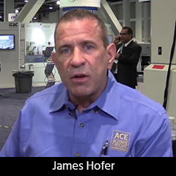
At DesignCon 2018, I spoke with James Hofer, general manager for Accurate Circuit Engineering, a quick-turn fabricator based in Santa Ana, California. James gave me a preview of AccuWrap, a new type of processing technology that lets designers reduce the amount of copper during sequential laminations while still meeting IPC specs, which should be of great interest to RF designers.
Andy Shaughnessy: Good to see you, James. Why don’t you just give us a quick rundown of the company?
James Hofer: Accurate Circuit Engineering has been a privately-owned company for the last 35 years. We’re family-owned, small, quick-turn, high-mix, high-tech, and low to mid-volume. We specialize in RF and microwave boards. We've got all the certifications. We're actually one of the few remaining small, privately held circuit board shops in Southern California, considering all the acquisitions that have been going on.
Shaughnessy: I understand you've got some really new cool technology to talk about.
Hofer: That's right. Over the last couple years, we've developed a trademarked process that allows us meet wrap requirements per IPC, while still maintaining low surface copper, which is important to our microwave and RF customers. We've labeled the technology AccuWrap, and its purpose is to be able to do multiple sequential laminations with blind vias while keeping the surface copper manageable.
The issue that we encounter is that nowadays, you do a lot of blind vias that might span one to two, then one to three, then one to five, maybe one to six on a 10-layer board. Then you've got through-holes that are filled. Each one of those blind vias and the through filled holes all require wrap. This is all before you actually get to your drilled holes, which also require wrap and plating.
With standard processing methodology, each one of those gets plated up for IPC-6012, for example, Class 3, and each one of those has to have a half mil of wrap. Typically, you'll start with a quarter or half ounce foil, but I just defined five different sets requiring wrap, that's an addition two and a half mils of copper that's going on top of your either ¼ ounce or .5 oz of base copper before you've even gotten to your through-hole plating. In an RF world, having that much copper on the surface, and we are talking about three mils, can be detrimental for your signals. So, ACE has been tasked with finding a way of meeting 6012 and 6018 specifications, yet still being able to build an RF board that engineers can model and work with.
So AccuWrap, in short, reduces the amount of surface copper that goes on the board, while still meeting the wrap requirements of the IPC specifications. It's taken a couple years for us to refine it, define it and of course trademark it. Actually, this is kind of a preview of coming attractions, because we won't be posting this news on our website for probably another 60 to 90 days. We're very excited about it, and it's going to allow us now to do RF and antenna boards that want to keep the copper down around 1.5 mils or 1 mil yet still meet all the wrap requirements.
I think this is really groundbreaking for the industry in standard methodology. We're very excited about it. I just thought I'd bring it out at this show and talk to you a little bit about it.
Shaughnessy: What sort of customers or final products would this appeal to?
Hofer: This is especially good for folks who are doing antennas. Antennas typically utilize a lot of blind vias, always utilize some sort of filled vias, they may also have some back drilling as well. So I'm thinking It's going to be fantastic for the antenna industry, and I think even some of our digital boards where we have stacked, sequential laminations that exceed nine laminations may benefit.
Now if I've got nine laminations, that's means I've got nine wrap requirements, not including the filled vias or the through-hole vias. Being able to reduce that copper and keep it closer to 1.5 or 2 mils is going to really make a difference for even your guys who are doing digital stuff with impedance because it's hard to have a five mil high trace and meet your impedance requirement, especially when most of your designers model that out at 1.5 mils or 2 mils.
So I think in that regard, in that market sector, our customers are going to see a real advantage.
Shaughnessy: That will really help the designers. So, you've obviously been working with IPC on this?
Hofer: Absolutely, as well as trademark attorneys all our process engineers and, of course, now it’s your turn. You're the marketing guys! You've got to let designers know that there is an answer. I think the issue is that we have a lot of PCB designers out there, and basically, when they model, they take the base copper that they get with a laminate and they assume that this is going to be the finished copper. A lot of RF designers model with what's known as base copper or foil weights and they don't realize how much copper can be added to the surface in standard manufacturing. I really am looking forward to getting the word out there that they can still meet the requirements of the specs and have copper that's manageable.
Shaughnessy: For designers, what are the biggest advantages of using AccuWrap?
Hofer: You can go with as many sequential laminations as you need to, without jeopardizing the amount of copper on your outer layers. A lot of designers get fearful that are aware of wrap that I can't do that because I can't have that much copper on the surface. The second thing I would let them know is that you can still do multiple sets of blind and filled vias while still being able to certify the board IPC.
Shaughnessy: That sounds like a pretty easy sell. Congratulations. It sounds like you're really taking care of a problem here.
Hofer: We've seen the problem and we found a solution. We provide solutions. We don't just provide circuit boards.
Shaughnessy: That's what people want.
Hofer: Yep. Thank you, Andy.
Shaughnessy: Thank you for speaking with us, James.


