


 Standard of Excellence: Speed vs. Quality in Customer Service
 Knocking Down the Bone Pile: Revamp Your Components with BGA Reballing
 Global Sourcing Spotlight: Balancing Speed and Flexibility Without Sacrificing Control


Shrinking Silicon, Growing Signal Integrity Challenges
March 9, 2023 | I-Connect007 Editorial TeamEstimated reading time: 2 minutes

What happens when die sizes shrink? As IPC design instructor Kris Moyer explains, quite a bit. Shrinking silicon can mean rising signal speed and rise times, and traditional PCB designers may find themselves dealing with problems formerly only seen by RF engineers.
We asked Kris to discuss the pros and cons of silicon shrinkage and some of the techniques and trade-offs that PCB designers and design engineers need to understand as they find themselves entering the RF arena.
Andy Shaughnessy: This issue focuses on the effects of shrinking silicon on a board’s signal integrity and EMI. So, what do PCB designers need to understand about die shrinkage?
Kris Moyer: Basically, the main thing that happens when you shrink the size of the die is that it shrinks the length of the channel of the transistors inside the die. What that effectively does is it increases the speed of the circuit, meaning it decreases the rise time or the fall time. Then you end up having to start treating your traces, geometries, and transmission lines almost as if they're RF designs.
We've heard for decades that RF designs are their own special little area of black magic, because we start dealing with all these waves and fields and so on. We say in digital design that it's the rise time and not the frequency. Which is the driving force, the key factor, that causes the need for all these high-speed designs? What is the frequency content?
Fourier's theorem says any wave form—square wave, triangle wave, sawtooth wave, or any wave form—can be recreated as a superposition of a sufficient amount of sine waves and cosine waves of sufficiently higher harmonics. Let’s take a fundamental frequency, 1 kilohertz. And you have A1, A3, A5 and A10 kilohertz. You have all these harmonics, we superimpose them, and you end up getting a square wave. Well, how square does that square wave need to be? This is the part that throws a lot of designers off.
When we talk about rise time, we're really talking about the time it takes that square wave, the digital signal, to change from a logic 0 to a logic 1. As the die shrinks, that time also shrinks. About 20 years ago, we were having rise times and fall times in the multiples of nanoseconds—five to 10 nanoseconds. It took that signal five to 10 nanoseconds to change from a logic 0 to a logic 1. I was just looking at one FPGA with rise times as fast as 0.25 nanosecond, and that's at 16 nanometers.
My friends who work in next-generation silicon at some of the big telecom companies are working in 5, 3, and 2 nanometer, and going sub 100 picosecond. Instead of 0.25 nanosecond, it’s 0.1 nanosecond and 0.05 nanosecond rise times. They’re such incredibly fast rise times that the number of harmonics we need to create a vertical square edge that transitions from A0 to A1 that fast means that the frequencies involved in that superposition in that Fourier series are up into the multiple gigahertz of frequency content. That means that you're in the RF frequency range.
To read this entire conversation, which appeared in the February 2023 issue of Design007 Magazine, click here.
Share on:


Testimonial
"Your magazines are a great platform for people to exchange knowledge. Thank you for the work that you do."
Simon Khesin - Schmoll MaschinenSuggested Items
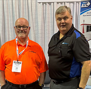
TTCI Brings Hands-On Test Engineering and IPC Training Expertise to PCB Carolina 2025
10/31/2025 | The Test Connection Inc.The Test Connection Inc. (TTCI), a trusted provider of electronic test and manufacturing solutions, and The Training Connection LLC (TTC-LLC) will exhibit at PCB Carolina on Wednesday, November 12, 2025, at the McKimmon Center at NC State University in Raleigh, North Carolina. Attendees can visit Table 4 to say hello to Bert Horner and Bill Graver, and learn more about their test engineering services and technical training programs.
The Training Connection Continues to Grow with Addition of Veteran IPC Trainer Bill Graver
10/30/2025 | The Training Connection LLCThe Training Connection, LLC (TTC-LLC), a premier provider of test engineering and development training, is proud to announce the addition of Bill Graver to its growing team of industry experts. A respected professional with more than 35 years in electronics manufacturing, Bill joins as an IPC Master Trainer, bringing a wealth of hands-on experience in PCB testing, failure analysis, and process improvement.
Electronics Industry Warns Mexico Tariffs Could Undercut U.S. Manufacturing and Supply Chain Resilience
10/24/2025 | Global Electronics AssociationAs negotiations over U.S.–Mexico trade policies near an October 29 deadline, the Global Electronics Association released a new policy brief, From Risk to Resilience: Why Mexico Matters to U.S. Manufacturing.
Knocking Down the Bone Pile: Revamp Your Components with BGA Reballing
10/14/2025 | Nash Bell -- Column: Knocking Down the Bone PileBall grid array (BGA) components evolved from pin grid array (PGA) devices, carrying over many of the same electrical benefits while introducing a more compact and efficient interconnect format. Instead of discrete leads, BGAs rely on solder balls on the underside of the package to connect to the PCB. In some advanced designs, solder balls are on both the PCB and the BGA package. In stacked configurations, such as package-on-package (PoP), these solder balls also interconnect multiple packages, enabling higher functionality in a smaller footprint.
New Course Presents a Comprehensive Guide to IPC Standards
10/10/2025 | Marcy LaRont, I-Connect007Francisco Fourcade, electronics technology standards manager for the Global Electronics Association, has spent years helping companies understand and implement the standards that keep the electronics manufacturing industry moving forward. In this interview, he shares updates on ongoing standards development efforts and previews a new course, "IPC Standards: A Guide for the Electronics Industry,” which starts Oct. 14.