


 Elementary, Mr. Watson: The Four Horsemen of Copper Confusion
 The Shaughnessy Report: Zee Plane! Zee Plane!
 Target Condition: Distribution of Power—Denounce the Ounce


Simplifying Simulation and Analysis
April 25, 2023 | Andy Shaughnessy, I-Connect007Estimated reading time: 6 minutes
Simulation has always been a critical step in the design process, and it’s only become more critical as design methodologies have become more complex. Gone are the days when simulation meant a simple logic simulation of your circuit, or a basic SPICE run to check signal waveforms. The simulation complexities that are required often fall “above the paygrade” of all but the most experienced members of a hardware design team. So how do you keep simulation from becoming a design bottleneck?
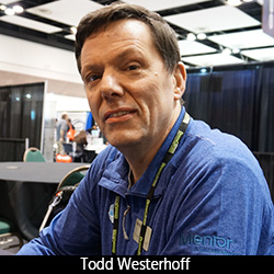
Todd Westerhoff, product marketing manager at Siemens, dives into the discussion with Andy Shaughnessy.
Andy Shaughnessy: Todd, what are some of biggest challenges you hear from your customers?
Todd Westerhoff: Lately we find ourselves asking customers, “What do you do once a board layout is complete, before you send the design out to prototype fab? How do you verify a design is ready for manufacture?” With signal integrity, we talk a lot about what goes into designing a board; the simulations we run to figure out the device placement and signal routing rules that drive physical design. The modeling and simulation process to define those rules can get incredibly detailed—in the end, what comes out of that process are routing rules.
The assumption with routing rules is that board designers will follow the rules completely and accurately. Once PCB layout is complete, what should you do? Take the designer’s word that the rules were followed and not do any checking? It’s fascinating the types of answers we get, but the most common answer is “We bring up the database in a viewer and eyeball it, then build it and test it in the lab.” With the complexity of today’s designs, that’s not optimal.
Shaughnessy: They might have budgeted for re-spins.
Westerhoff: Sure, but as you go faster and the constraints get tighter, the problem is that there are hundreds or thousands of signals on the board that need to follow high-speed rules. But somewhere, somehow, it seems that deviations are required, because the rules can’t be followed explicitly. There’s something in the way like a mounting hole, or the board dimensions have been changes, or the stackup has been modified for some other reason. The point is, the chance that all the rules get followed without exception is fairly small.
In the integrated circuit (IC) space, we wouldn’t even consider taping out an IC without running extensive post-route verification. That would be crazy, given the cost of the die masks. But in the board space, we do it all the time. We spot check a handful of signals with simulation if we simulate anything at all, then we use visual inspection of the board layout to look for possible problems. Visual inspection is problematic—it’s boring and tedious; we get tired, and we make mistakes.
Some customers say, “We don’t have the skills in-house to run modeling and simulation, so we get a contractor to analyze the design.” That approach is expensive, but functional, except - what happens when the contractor comes back with problems that need to be fixed? Are you going to fix those issues and then pay them to analyze the design again? That loop time quickly gets both long and expensive.
Ideally, designers have signal integrity experts in their company that can do the modeling and simulation needed to verify the design. The problem there is, those signal integrity experts are probably already completely overloaded. You know that picture of climbers standing in a long line to get to the top of Mount Everest? That’s probably what it feels like trying to get time from an in-house signal integrity expert.
At Siemens, we’re focused simplifying and automating post-route PCB verification. Verifying all the design’s critical signals after routing is possible with our tools, instead of only verifying a handful of signals, which is what happens with other tools. Full-system post-route verification is a particular strength for Siemens and HyperLynx.
Shaughnessy: If you ask designers, they’ll say you should definitely do it.
Westerhoff: True. But there’s a difference between wanting to do something, or acknowledging it should be done, and actually doing it. We all know we should floss regularly, but how many of us actually do it? The fact is, post-route verification with most signal integrity tools is a tedious and manual process, so most designers limit their efforts to spot-checking, if they simulate at all. We’re focused on automating verification from to back and making the process more accessible to system designers who aren’t full-time signal integrity experts.
At DesignCon 2023, we demonstrated post-route verification of serial links at the full system level. We used a reference design for the fourth generation Intel Xeon processor—a server motherboard that has 336 PCI Express Gen 5 serial channels operating at 32 Gb/s. We showed how to model and simulate every single one of those channels to verify what the operating margin is. This is what we mean by full system, post-route verification.
The odd thing is that PCB signal integrity got its start 30 years ago through post-route verification. Back then, you would lay out the board, simulate your critical signals to find issues and then fix them. As speeds increased, more signals became critical and pre-layout analysis became more important. Post-route verification has faded over time because most tools don’t support it very well, so people have decided it’s just too hard to do. But it still works just fine, and we’re bringing it back.
The question has become – how can we make analysis available to the broader community, and make it practical for people who aren’t full-time signal integrity experts? The trick is identifying specific simulation flows that will help hardware designers make design tradeoffs and verify them. You offer those analytical flows in an “easy” mode—sort of the analytical equivalent of an airplane’s autopilot. You make it possible for hardware designers to those analysis flows themselves.
You have to be practical: signal integrity can be complicated, and when you offer simpler analysis flows that designers can run themselves, eventually those designers will run into a problem where they get stuck. How do they get unstuck? HyperLynx lets novice and expert users run with the exact same models and data. If a designer runs into a problem using a targeted flow, the expert user can load that same design into full HyperLynx, dig into it, figure out the issue and get the designer going again. We’re trying to create two different use models: one for the everyday user and one for the expert.
Going back to the airplane analogy: I can’t fly a 737 because it’s just too complicated. That said, I can successfully fly and land a simulated 737 with an autopilot and a little help. It’s pretty easy to fly a 737 on autopilot with a little training. But when the going gets rough, the autopilot kicks off and you had better know how to fly that plane on your own. Now clearly, you can’t put an inexperienced pilot in an airplane, but we can give a less experienced user a design tool with simplified analysis flow, with a plan to back them up. Our customers are creating complex, proprietary designs; they’re not about to send their designs to us for debugging. The two-use model approach lets them get support from expert users within their own organization.
Shaughnessy: That’s great. The democratization of signal integrity.
Westerhoff: That’s exactly what we’re trying to do. Many longtime specialists in this field are starting to retire; there simply aren’t enough experts to go around, and the technical issues continue to get more complex. We need to start thinking about different classes of analysis tools for different types of users.
Shaughnessy: Todd, this is a great idea, and it’s all part of “left-shift” as well. Great talking to you, as usual.
Westerhoff: Thanks, Andy.
Share on:


Testimonial
"Your magazines are a great platform for people to exchange knowledge. Thank you for the work that you do."
Simon Khesin - Schmoll MaschinenSuggested Items
Advanced Electronics Packaging Digest: Third Issue Arrives November 17
11/12/2025 | I-Connect007The third issue of Advanced Electronics Packaging Digest launches Monday, November 17. This issue continues AEPD’s mission to deliver forward-looking analysis and insider perspectives on the technologies reshaping advanced electronics packaging. Among the highlights is a review of IMPACT 2025, where discussions on component-to-system-level integration took center stage as experts explored the challenges and breakthroughs driving advanced packaging technologies.
Electronic Design Automation (EDA) Market Size to Reach $811.1 Million by 2030
11/12/2025 | PRNewswireThe Global Electronic Design Automation (EDA) Market was estimated to be worth USD 541 Million in 2023 and is forecast to a readjusted size of USD 811.1 Million by 2030 with a CAGR of 6.4% during the forecast period 2024-2030.
The Technical Backbone of an EMS Company: A CEO’s Perspective
11/12/2025 | Jay Rupani, Precision PCBAs the CEO of an EMS company, I often say that our business runs on precision, innovation, and trust. Behind every finished product—whether it’s a medical device, an automotive control module, or a consumer gadget—lies a sophisticated technical ecosystem that makes it all possible. From design support and process engineering to automation, data analytics, and supply chain integration, the technical side of EMS is where our value truly shines.
ASE Unveils IDE 2.0 – AI-Enhanced Platform Accelerates Package Design Accuracy and Innovation
11/12/2025 | ASE GroupAdvanced Semiconductor Engineering, Inc. (ASE), a member of ASE Technology Holding Co., Ltd., announced the launch of IDE 2.0, a major upgrade to its Integrated Design Ecosystem™ (IDE) platform.
Elementary, Mr. Watson: The Four Horsemen of Copper Confusion
11/12/2025 | John Watson -- Column: Elementary, Mr. WatsonIf there were a PCB Design Dictionary of Confusing Terms, the cover would feature four words that have baffled generations of engineers: polygons, pours, planes, and floods—or what I refer to as the four horsemen of copper confusion. They sound simple, as if they belong in a geometry textbook or a weather report, but in PCB design, they overlap, develop, and sound interchangeable until you realize they aren't.