















 Fresh PCB Concepts: Managing PCB Trace Width and Spacing
 Elementary, Mr. Watson: The Rise and Fall of Europe's PCB Design Community
 Connect the Dots: What PCB Designers Should Know About Materials





Chapter 1: How We Got Where We Are
The Paradox of DFM
Before the development of PCB computer-aided manufacturing (CAM), the process of preparing a board for fabrication and assembly was as cumbersome as actually designing the board itself. Early PCB manufacturing involved several manual processes which remain largely intact today, mirrored by a modern digital equivalent. Manual design for manufacturing (DFM) began with PCB artwork that was produced by applying an opaque film on a clear piece of mylar. The examination and measurement process involved using an eye loupe, and any necessary edits were made by either carefully scratching off the tape with an X-ACTO® knife to provide additional clearance or filling in voids with a black marker.
Tasks such as drilling and component placement relied on custom-built mechanical programs. These were stand-alone solutions, created individually in a time-consuming and painstaking process involving specialized equipment such as drill bomb-sight machines. With such an intensive and manual process, there were many challenges to overcome to meet all the necessary operational complexities needed to produce a circuit board.
As the complexity of systems increased, these physical sheets were replaced by digital files, but the manual complexities persisted.
During the 1980s, the design data transferred to manufacturing facilities was heavily split as a result of the myriad of solutions necessary to produce a PCB. Gerber data was used for artwork, Excellon drill format for mechanical drilling, typically a centroid file which assisted in component placement and, if you were very lucky, a netlist file in IPC-356-A format was included. This data came accompanied by a corresponding component bill of materials.
The objective of the PCB CAM system was to reverse engineer that collection of files back into a semblance of what originated in the initial design application. Shortly after these PCB CAM systems began reconstructing the design, manufacturers began to realize the potential in evaluating the PCB—only this time from their unique manufacturing perspective.
PCB CAM was created to optimize the process of transferring a design to manufacturing. The manufacturing process capabilities were assembled into Engineering Rules Files (ERFs), with multiple ERFs created based on the technology present within the design. Fabricators would often modify the design data to improve the overall quality, yield, and reliability of the final PCB. The use of generated artwork by photoplotters meant both the previous manual operations, as well as the mechanical programs, became obsolete.
At this point, Electronic Design Automation (EDA) solutions were focused on the PCB’s electrical requirements rather than its manufacturability. Even now, you often see this manifested when PCB designers “throw the design over the wall.” This could be more accurately stated as “let the manufacturers deal with it” or “my manufacturers do that!” This sentiment of making it someone else’s problem is a mantra I still hear repeated by designers to this day. Whether this line of thinking is further exasperated depends on when in the manufacturing process the issues occur. If the issues are related to assembly and identified after fabrication, then a corrective design modification is too late. This could lead to the use of expensive process variation which may require specialized tooling, such as a step stencil, adding additional manpower resulting in higher cost, and could negatively impact yield, quality, and reliability.
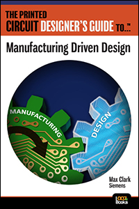
"Is this really DFM?" asks the author. Continue reading The Printed Circuit Designer's Guide to... Manufacturing Driven Design to find out his answer to this question.


