


 Designers Notebook: Layer Stackup Planning for RF Circuit Boards
 Connect the Dots: Involving Manufacturers Earlier Prevents Downstream Issues
 Global PCB Connections: The Next Wave of HDI PCBs– How Design Engineers Can Stay Ahead


Accelerated Reliability Testing: Interconnect Stress Testing vs. Accelerated Thermal Cycling
September 5, 2012 |Estimated reading time: 8 minutes
Editor's Note: This article originally appeared in the July 2012 issue of The PCB Magazine.
 The industry’s transition to lead-free materials means that the reliability of many new materials must be tested, preferably quickly, for lead-free assembly applications.
Two accelerated reliability test techniques, the more traditional air-to-air accelerated thermal cycling (ATC) and newer interconnect stress testing (IST), are commonly used to assess circuit board interconnects and, more specifically, the performance of plated through-hole vias.
But exactly how closely do ATC and IST results align? Can IST, which is much faster than ATC, be used reliably in place of ATC for future laminate and plated through-hole testing?
The High Density Packaging User Group (HDP User Group, or HDPUG) consortium decided to evaluate new lead-free materials using both ATC and IST to do a correlation study as one facet of its Lead-free Board Materials Reliability Phase II project. The primary goal of this particular facet was to correlate IST to ATC, which would then enable correlation to field conditions, which is possible with ATC.
Since many boards now contain more than 60,000 drilled vias, a high failure rate isn’t required to translate into a significant problem. Via reliability is a key issue and, while IST was known as a good tool for evaluating plating, prior to this study, there was limited confidence that it could be used reliably to rate the field reliability impacts of lead-free assembly processes or evaluate the impact of different materials on the via reliability.
An earlier HDPUG study revealed issues with correlating IST to ATC, which were caused in part by the suitability of the selected IST coupon design for the high-layer test vehicle constructions evaluated. Although not apparent at the time, but later proven, was the influence of the glass transition temperature (Tg) in the results—particularly for materials with a low-Tg value.
Lead-free Board Materials Reliability Phase II
To begin Phase II of the study, design changes were made to the IST test coupons to improve heat distribution.
First, for background, IST works by passing a predetermined constant DC current through a specifically designed PCB interconnect test coupon, and the current elevates the temperature of the metals and adjacent materials. The temperature to which the coupon is heated is directly proportional to the measured resistance and the amount of the current passed through the conductors, pads and vias.
Test vehicle improvements also included modifying the design to add a specific area for dynamic mechanical analysis (DMA) testing; implementing plane capacitors in the IST coupons that enable capacitance measurements to determine product construction; estimating dielectric spacing; and determining if material damage was caused during assembly. Also, coupons were modified to ensure consistency in the geometries and layout between the IST and ATC test sections, expanding the focus of the IST and ATC designs to address via pitch in greater detail, and adding custom-designed IBM-style WIC-20 coupons for material analysis and moisture sensitivity testing.

Figure 1: The MRT-5 PBC design.
MRT-5’s two IST coupons are specifically designed material analysis coupons with 0.25mm-diameter drilled via holes. One coupon has 1mm via to via spacing, while the other has a 0.8mm via spacing. The ATC section has four sets of vias arranged in eight chains of 50 vias each. The first three sets have 0.25mm drilled via holes with via spacing of 2.54mm, 1mm, and 0.8mm, respectively. The fourth set of eight daisy chains uses a 0.66mm drilled hole size on a 2.54mm via-to-via spacing. The via chains on 1mm and 0.8mm pitch in both the IST and ATC sections are designed identically—they use the same hole sizes, including the use of nonfunctional pads, etc. 1
Evaluation
The study focused on 27 different lead-free constructions, using 20 different lead-free materials, built by three PCB manufacturers. Materials were evaluated using both IST and ATC methods with test vehicles that combined via reliability and materials analysis capabilities.
In terms of construction, all products were built with 20 layers, laminated to an average thickness of 2.92mm, and drilled with 0.25mm vias—producing an aspect ratio of 11.5:1. All 20 materials were built with the standard resin content construction. Seven selected materials were also built in a high resin content construction and different glass styles to represent higher layer-count boards in the same thickness.
Testing in both ATC and IST was carried out on specially designed coupons preconditioned to simulate six passes through a typical inline convection reflow oven with a peak temperature of 260°C +5°C/-0°C. The materials were IST tested on two coupon types—both as-built and after 6x lead-free (260°C) reflow.
After 6x reflow, the materials were tested in both ATC (from -40°C to +135°C as measured on the boards with 10-minute dwell and ramp times) for 6000 cycles and IST (from ambient 23°C to 150°C with three-minute heating ramps, two-minute cooling ramps, and no dwell at either temperature extreme). IST testing was initially continued to a maximum of 3000 cycles, but extended to 6000 cycles on materials that proved to be robust.
Analysis Results
The results of the ATC and IST thermal cycles were compared by regression analysis after 6x assembly reflow. To ensure a valid comparison, only the 1mm pitch results from each test were compared, and any materials with major delamination defects were excluded from the analysis to avoid misleading results.

Figure 2: This scatter chart shows the correlation between ATC and IST, with three outliers circled.

Figure 3: This scatter chart shows a strong correlation between ATC and IST, once materials with a Tg at or below 150°C are filtered out.
Outliers
Three interesting outliers were discovered and determined to be caused by materials’ properties changing at approximately 150°C. These outliers are unique in that they were materials where the Tg by DMA storage modulus was at approximately 150°C or lower, as measured on the multilayer board after 6x reflow.
The testing peak temperature of ATC was 135°C, compared to the 150°C peak temperature of IST. The IST testing for these outlier materials is at or above the Tg. The same effect—poor IST performance compared to ATC—was also identified on the other two low-Tg materials’ results, although it wasn’t initially obvious from the plot of the data. All of the other materials had a Tg significantly higher than 150°C, and the correlation between IST and ATC was very good.
Tg: a critical parameter affecting long-term reliability
What does this data suggest for long-term reliability testing? Since the IST peak temperature is 150°C and at or above the Tg by DMA storage modulus, the peak temperature of IST testing should be reduced to below the Tg of the finished multilayer board. Based on our data, a 10°C reduction in the peak test temperature appears to be an adequate reduction. Otherwise, the plating reliability will be estimated to be much lower than it actually is for typical applications where the operating temperature doesn’t approach the Tg of the material. For applications with high peak operating temperatures, such as automotive ones, the Tg appears to be a critical parameter affecting long-term reliability and higher-Tg materials may be required.
Correlation Found
When the material Tg, specifically as measured by DMA storage modulus, is below the testing temperature of both IST and ATC, then IST and ATC correlate closely and IST can be used as an alternative to ATC for field life predictions. For thick boards, as used in this study, the IST design must have heating elements distributed through the material stackup to ensure even heating of the IST coupon and good correlation to the ATC testing.

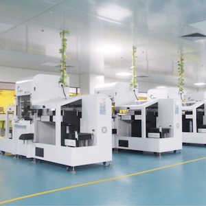
Figure 4: Typical IST testing station.
These findings are highly significant because it means that IST can be used for long-term reliability estimates in future laminate test programs—saving months of time.
Speed Factor
Speed of reliability testing is a critical factor in evaluating and leveraging the benefits of new materials in next-generation designs. Because several thousands of cycles are usually needed, ATC test times of six months or more are not uncommon. IST is considerably faster. In our project, for example, a 6000-cycle test takes IST 20.8 days, while ATC takes 166.7 days.
IST’s speed is attractive when you’re trying to get a product to market quickly or qualifying a new material. But it’s important to note that the biggest drawback to IST is a small sample size of typically six coupons, although newer machines can now handle larger numbers. One key benefit of ATC is that you can simultaneously run a considerably larger sample size, but it will take much longer.
Value
The industry clearly sees the value in this type of testing through a consortium. The lab tests involved in this entire project—which included other facets not discussed here—were conservatively on the order of $1M, which pays back quickly on reliability issues that would ultimately betray you in the field. For example, our testing program highlighted potentially costly performance and reliability issues with certain materials that has previously gone unidentified during supplier qualifications.
This project was a huge collaborative effort that involved not only the support of a large number of HDPUG’s 36 member companies, but significant input from leading material suppliers in the industry as well. And since so many member companies were involved and offering specialist resources, the overall cost to each member to get important test data was a relatively small piece of the overall $1M.
What’s Next?
Based on the findings of the Phase II project that IST is indeed reliable on its own, HDPUG has already begun work on Phase III—focusing on halogen-free and high-speed materials. A total of 13 different laminates are being tested with two constructions—high resin and lower resin materials—and evaluated for each product.
Phase III is eliminating the requirement for ATC and using only IST to complete testing on a much faster timescale, which will allow members to quickly get important and independent performance data about new laminates.
Acknowledgement
Thanks to the HDP User Group and member companies for their support and assistance with this work. Special thanks to Bill Birch of PWB Interconnect Solutions for his time and resources.
Reference
1. Joe Smetana, et al., “Reliability Testing of PWB Plated Through Holes in Air-to-Air Thermal Cycling and Interconnect Stress Testing After Pb-free Reflow Preconditioning,” Proceedings of IPC/APEX, Las Vegas, NV, April 2011, pp. 2255.
Joe Smetana is a principal engineer, Advanced Technology, at Alcatel-Lucent. His work addresses device and system packaging, interconnection, PCB fabrication, PCB assembly, and system integration covering design, manufacturing, reliability, and signal integrity. He has been the team leader on several successful HDP User Group projects.
Share on:


