


 Elementary Mr. Watson: Running the Signal Gauntlet
 The Shaughnessy Report: Winning the Signal Integrity Battle
 Connect the Dots: How to Avoid Five Common Causes of Board Failure


Latest Articles
EMA is Bullish on Data Management

EMA Design Automation has evolved over the years, from a typical Cadence Design Systems VAR to a distributor that functions more like a part of Cadence. During DesignCon, I met with Greg Roberts, director of marketing for EMA, and asked him to discuss the company’s focus on data management tools, and why he’s giving away certain OrCAD tools.
Quiet Power: Dynamic Models for Passive Components

A year ago, my Quiet Power column described the possible large loss of capacitance in multilayer ceramic capacitors when DC bias voltage is applied. However, DC bias effect is not the only way we can lose capacitance. Temperature, aging, and the magnitude of the AC voltage across the ceramic capacitor also can change its capacitance. This column will provide all of the details.
IMPACT Washington, D.C. 2016: Industry Leaders Advocate for a Pro-Manufacturing Policy Agenda

IPC places a high priority on educating government officials about key policy issues of importance to the electronics industry. That’s why top executives from leading electronics companies gathered in Washington, D.C. recently for “IMPACT Washington, D.C. 2016.”
Design Strategies for Success—and Profit

In today’s economic environment, making money on a project is getting more and more challenging. Those years when businesses like mine were practically printing money are long gone. If you are under 30 years old, you probably do not have this point of reference; it’s been one downturn after another for your entire adult life. But for us older folks, times were really good back then. So, what happened? You happened, as well as a million others like you. In other words, the market is a little cramped now and much more competitive, which dilutes our profit per project.
Brooks' Bits: How Many Vias Does It Take To…?

During 2015, I enjoyed a very productive collaboration with Dr. Johannes Adam, from Leimen, Germany. This resulted in several papers, but one in particular is relevant for this column, “Via Currents and Temperatures.” In that paper, we used a simulation tool, thermal risk management, developed by Dr. Adam, to simulate current flowing through a via and then determine the temperature of the via. Read on to find out how our results contradicted conventional wisdom.
Sunstone Circuits R&D: 3D Printing Great for Prototyping

We’ve been hearing a lot about 3D printing for the past few years. But where does 3D printing fit in with traditional rigid circuit board development? Sunstone Circuits recently completed a project that focused on that very question. Sunstone Product Manager Nolan Johnson explains why 3D printing is a viable option when it comes to jigs and parts of the support infrastructure that are needed when prototyping today’s emerging technologies.
Happy’s Essential Skills: Technical Writing

Technical writing is one of those topics that they don’t really talk about in college—at least not where I went. Writing and English has never been a strong like of mine compared to science and math. So I did my required time in English and wrote my lab reports the best I knew how.
Beyond FR-4: High-Performance Materials for Advanced Designs, Part 1

In the past 40-plus years of PCB manufacturing, the primary material of choice has overwhelmingly been e-glass supported FR-4 resin laminates. This is due to the excellent dimensional stability and reasonably acceptable thermal performance (based on glass transition temperature [Tg] and decomposition temperature [Td]). In general, these materials exhibit impressive performance and excellent cost for a wide range of applications.
Beyond Design: The Need for Speed—Strategies for Design Efficiency

Years of experience with one EDA tool obviously develops efficiency, whether the tool be high-end feature-packed or basic entry-level. And one becomes accustomed to the intricacies of all the good and bad features of their PCB design tool. However, there comes a time when one should really consider a change for the better to incorporate the latest methodologies. This month, I will look at productivity issues that impede the PCB design process.
Weiner’s World

3D printing, China’s SMT equipment and robotics markets, IPC’s mandate, counterfeiters, and Taiwan PCB makers’ shift to automotive electronics—Gene Weiner talks about these things and more in this new article.
RTW IPC APEX EXPO: Mentor Graphics Takes Manufacturing Operations to the Next Level

Dan Hoz, general manager of Mentor Graphics Valor Division, discusses with I-Connect007's Andy Shaughnessy how they are helping electronics manufacturers take their operations to the next level through their Valor IoT Manufacturing solutions. He talks about the OML and the Valor IoT Device, and how these solutions will help the electronics manufacturing industry to move to Industry 4.0.
Designers Notebook: Flexible and Rigid-Flex Circuit Design Principles, Part 5

The outline profile of the flexible circuit is seldom uniform. One of the primary advantages of the flexible design is that the outline can be sculpted to fit into very oblique shapes. This month, Vern Solberg focuses on outline planning, physical reinforcement, and accommodating bends and folds in flexible and rigid-flex circuits.
Tim's Takeaways: The Principles of Hybrid Design, Part 1

What exactly is a hybrid design? We are seeing more and more of our customers exploring the world of hybrid design, and we are getting new customers for whom hybrid design is their sole focus. The world of hybrid design is growing and we have lots of hybrid-specific functionality built into our software that helps designers conquer the unique hybrid design requirements.
The Bare (Board) Truth: The Top 10 Ways Designers Can Increase Profits

So, can you truly increase profitability through PCB design practices? Prototron's Mark Thompson believes you can. And it starts with a philosophy that embraces DFM techniques. Then you must be ready for the initial release to a fabricator by ensuring that you are communicating all of your specifications and needs clearly to the fabrication house so that you get an accurate quote. Let’s dive in, starting with Number 10 and working our way to the most important way a designer can increase company profits.
Wild River: Simplifying SI so Engineers Can Focus on Design

Al Neves is founder and chief technologist of Wild River Technology, and he’s a signal integrity engineer who likes to tell it like it is. So when I bumped into Al during DesignCon, I asked him to sit down for an interview. We discussed the paper he co-wrote for DesignCon and the challenges SI engineers are facing, as well as Wild River’s efforts to take the black magic out of signal integrity.
RTW IPC APEX EXPO: HDP Users Group Update with Jack Fisher

Jack Fisher, technical director for the High-Density Packaging Group, discusses the latest projects that the consortium is focusing on. He explains that member companies have full access to all of the R&D data that is developed. One of the group's most interesting current efforts involves optoelectronics.
RTW IPC APEX EXPO: Geek-A-Palooza Coming to S. California May 12
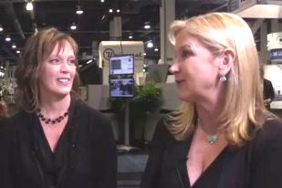
Steve Williams sits down with Geek-A-Palooza founders Tara Dunn and Judy Warner to discuss their upcoming event in Irvine, California on May 12. The Geek-A-Palooza held in Minneapolis last year drew over 300 PCB designers, fabricators, assemblers and suppliers. Tara and Judy explain why this is not just another boring technical talk, and attendees will definitely enjoy themselves.
Steinberger Talks PAM4, the Next Generation of Modulation

I recently interviewed our old friend Michael Steinberger, SiSoft’s lead architect for serial channel products. Steinberger is always a great interview; he breaks down complex signal integrity simulation technology in ways that are simple and often humorous. Steinberger sat down and discussed a paper he presented at DesignCon, and some of the challenges his customers are facing.
RTW IPC APEX EXPO: Mentor Graphics Makes Internet of Manufacturing Affordable

Michael Ford, marketing development manager at Mentor Graphics, and I-Connect007 editor Andy Shaughnessy discuss the Open Manufacturing Language (OML), the challenges in supporting the hundreds of thousands of machines that are out there at shopfloors already, and how Mentor is making the Internet of Manufacturing affordable for everyone in the PCB assembly supply chain.
IPC APEX EXPO: Isola Introduces New Products, Increases R&D

Ed Kelley, VP of global technology, sits down with Guest Editor Dan Beaulieu at IPC APEX EXPO to discuss the company's plans for the future. The company is launching new low-loss laminates and increasing its R&D activities around the globe. He also explains why Isola often works with designers at OEMs.
IPC APEX EXPO: IPC Government Relations—Your Advocate in Washington
IPC's VP of Government Relations, John Hasselman, explains IPC's "meet the policy makers" initiative (site visits by congressmen) to help build and broaden relationships with these decision makers.
IPC APEX EXPO: Gary Carter on First Board Manufactured With IPC-2581B

Gary Carter, senior manager of CAD engineering for Fujitsu Network Communications, discusses the first board fabricated and assembled using IPC-2581B. This 20-layer board features 21,000 component pins and 15,000 holes, with controlled impedance on all layers. He also gave a presentation on IPC-2581B during the Design Forum.
IPC APEX EXPO: EPTAC Updates on Soldering Committee Developments

Leo Lambert, vice president and technical director at EPTAC Corp., provides I-Connect007 guest editor Joe Fjelstad an update on some of the standard developments at IPC's soldering and assembly committee.
What’s New at Cadence?

Cadence Design Systems has released a variety of PCB design tools lately, and we wanted to find out a little more about what’s new at Cadence. I tracked down Product Marketing Director Brad Griffin and asked him to discuss some of the newest technology coming out of Cadence.
Standard of Excellence: Tips for Finding a Great PCB R&D Partner

This new column, Standard of Excellence, represents a cooperative writing effort by a team of experts at American Standard Circuits. This month, we begin with CEO Anaya Vardya, who focuses on R&D. In his piece, he provides his insights on what characteristics to look for in a good R&D PCB fabrication vendor partner, and a few things that are expected of them to do for you.
Catching up with…PNC: Open House Planned for May

I’m a great believer in open houses. Any time customers and vendors get together to learn and talk about what they can do for each other it’s a good thing. That’s why, when I heard that PNC, in Nutley, New Jersey, planned to hold an open house on May 20, I wanted to learn more about it. So I called my friend Sam Sangani, the company’s owner, to learn more about it.
IPC APEX EXPO: New Arlon Materials Address Design and Fab Challenges
Brad Foster, VP and general manager of Arlon, discusses some new laminates and pre-pregs that help designers and fabricators address a variety of challenges. He explains how Arlon works with customers to help them with stack-ups and other issues.
Walt Custer Elaborates on his Annual IPC APEX EXPO Forecast Presentation

IPC APEX EXPO 2016 has come and gone, and this year, Walt Custer’s annual presentation forecasting the upcoming year for the industry was much anticipated, as always. I met up with Walt at the show to learn about his presentation and dig deeper into his findings.
IPC APEX EXPO: Electrolube to Educate PCB Designers on Coatings

Phil Kinner, technical director of coatings for Electrolube, discusses a paper on condensation testing that he presented at IPC APEX EXPO, and his plans to educate PCB designers about conformal coatings to help them avoid problems during manufacturing.
What’s New at Zuken?

Zuken has developed some innovative PCB design tools in the past few years, and I wanted to find out more about the company’s new and upcoming technologies. I caught up with Bob Potock, vice president of marketing for the Americas for Zuken USA, and asked him what was new at Zuken.
The PDN Bandini Mountain and Other Things I Didn’t Know I Didn’t Know

Originally, Bandini Mountain referred to a mound of fertilizer built by the Bandini Fertilizer Company in California prior to the 1984 Los Angeles Olympics. When the company went bankrupt, this mound of fertilizer was left behind. Steve Weir coined this term to describe the large resonant frequency peak formed by the parallel combination of the on-die capacitance and the package lead inductance, as seen from the die looking into the PDN.
Designers Notebook: Flexible and Rigid-Flex Circuit Design Principles, Part 4
All of the design rules for the glass reinforced-portion of the board (land pattern geometry for mounting surface mount devices, solder mask and the like) are now well-established. One unique facet of fabricating the rigid-flex product is how the flexible portion of the circuit is incorporated with the rigid portion of the circuit. As a general rule for multilayer PCB design, furnish a balanced structure by building up the circuit layers in pairs (4, 6, 8 and so on).
IPC APEX EXPO: Prototron Works with Customers to Stay on Top

Prototron Circuits Operations Manager Mike Graves explains how his company's focus on customer service, including helping with PCB designs, has made Prototron "America's Board Shop." He also discusses their expansion into flex and HDI technology, and their efforts to achieve AS9100 certification.
IPC APEX EXPO: IPC's Fern Abrams Provides Updates on RoHS, REACH Directives

Fern Abrams, director of regulatory affairs and government relations at IPC, discusses with I-Connect007's Stephen Las Marias the latest updates on the changes happening in the RoHS and REACH directives this year, as well as IPC's new initiatives and advocacies.
IPC APEX EXPO: Hofer Discusses the Pros and Cons of Backdrilling

General Manager James Hofer of Accurate Circuit Engineering discusses the process of backdrilling vias, including the benefits and drawbacks. Backdrilling can improve signal integrity, but it can also create stubs that may act as unwanted antennas.
What’s New at DownStream?

Since its founding in the uncertain days of 2002, DownStream Technologies has made a name for itself with its line of PCB design post-processing tools. Founder Rick Almeida gives us an update on the latest innovations at DownStream, and he discusses some of the challenges and trends he sees in the PCB design segment.
Patricia (Patty) Goldman Inducted into IPC Hall of Fame
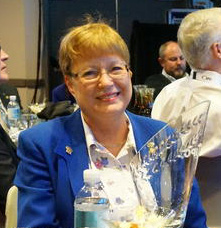
We at I-Connect007 are thrilled that our own Patty Goldman has been awarded the highest level of volunteer recognition that IPC can give to an individual, the Raymond E. Pritchard Hall of Fame Award. The award is given in recognition of superior achievement, extraordinary contributions and distinguished service to IPC and the advancement of the electronics industry.
IPC APEX EXPO: Clyde Coombs Discusses the New Printed Circuits Handbook

In this interview that was shot during the IPC APEX EXPO 2016 in Las Vegas, Nevada, Clyde Coombs discusses the latest edition of the Printed Circuits Handbook, which was published this week. The seventh edition, co-edited with Happy Holden, includes new sections on supply chain management and PCB design, with a chapter on EDA tools by Design007 Editor Andy Shaughnessy.
IPC APEX EXPO: Glenn Oliver on His IPC 'Best Paper' on High-Frequency Materials
Glenn Oliver of DuPont discusses his award-winning paper, “Round Robin of High-Frequency Test Methods by IPC-D24C Task Group." Co-authors include Jonathan Weldon of DuPont, John Andresakis of Park Electrochemical, Chudy Nwachukwu of Isola, John Coonrod of Rogers Corporation, David L. Wynants of Taconic Advanced Dielectric Division, and Don DeGroot of Connected Community Networks. The paper looks at high-frequency offerings from a variety of materials providers.
Mark Thompson: It’s All About Communication
In engineering support at Prototron Circuits, Mark Thompson has seen it all. He ensures that each design is manufactured the way the designer intended, even if the CAD data is not crystal clear. During DesignCon, Barry Matties and Andy Shaughnessy talked with Thompson about why communication is paramount when designing and prototyping boards. Thompson also explained how designers can avoid making common mistakes that can set back an entire project.
Mentor Graphics’ Oren Manor Explains Exactly What Industry 4.0 Brings to Manufacturing

Oren Manor of Mentor Graphics talks about what Industry 4.0 is really about, and how it benefits electronics manufacturers. He also discusses their design to manufacture solution, and how it helps OEMs large and small make the transition to Industry 4.0 without a complete factory overhaul.
Manufacturing Institutes Can Boost the Nation

In his most recent State of the Union address, President Obama highlighted a remarkable trend of recent years: the turnaround in many corners of America’s manufacturing sector. Nearly 900,000 new jobs have been created by U.S. manufacturers in the last six years.
Beyond Design: Faster than a Speeding Bullet

In optical communications, electrons don’t carry the signal—photons do. And we all know that photons travel at the speed of light. So surely, optical fibers must transmit information much faster than copper wires or traces on a multilayer PCB? Actually, photons and electrons transmit data at the same speed. The limiting factor is the relative permittivity (dielectric constant) of the medium in which the signal propagates.
Technology Outlook with Mentor Graphics

Mentor Graphics recently announced the winners of its PCB Technology Leadership Awards. Now in its 26th year, this program provides a great barometer for measuring the newest trends in cutting-edge PCB designs. I caught up with Product Marketing Manager David Wiens and asked him to give us an idea of the trends he’s seeing in PCB design and manufacturing, and what the industry has in store for us in the next few years.
Designers Notebook: Flexible and Rigid-Flex Circuit Design Principles, Part 3
This installment of "Designers Notebook" will focus on methods for specifying base materials, and also address copper foil variations and fabrication documentation. It is important to research the various products in order to choose the one that best meets the design requirements.
Catching up With Tom Hausherr of PCB Libraries

When fate placed Tom Hausherr and I at PCB West, we made sure to carve out some time together. Tom agreed to have a long breakfast with me so I could learn more about the challenges related to component libraries and how his company addresses these issues. So, pull up a chair and join us for a chat.
DuPont, Taconic and PFC Team Up For High-Speed Flex
At DesignCon, I sat down with three flex circuit specialists: Glenn Oliver of DuPont, Tom McCarthy of Taconic, and Steve Kelly of PFC Flexible Circuits. Our discussion covered a lot of territory, most notably the findings they described in the paper they were about to present later that day at DesignCon, and the future of flex, as they see it.
Enhancing Thermal Performance of CSP Integrated Circuits

In order to meet size and weight requirements, constraints of portable electronic designs often force PCB designers to reduce the size of components and PCB real estate area. To meet these demands, the use of CSP packages to shrink the PCB area needed is a common change in designs. As a result of the reduction of total PCB area, the available options to move heat and route high-power PCB traces is also reduced. Furthermore, the thermal performance cannot be matched when a QFN is compared to an equivalent CSP package.
The Shaughnessy Report: Doing My Part for Medical Electronics
One interesting aspect of having hernia surgery recently was the number of PCBs in the operating room. I’ve never seen so many electronic devices together in my life. I saw one Agilent monitor, and a bunch of others with names I couldn’t make out. It reminded me of the IT room in most companies. I guess they had to be set up to handle routine surgery like mine, and the not-so-routine operations as well. Medical electronics is doing fine, no doubt.
Designers Notebook: Flex and Rigid-Flex Circuit Design Principles, Part 2
In this installment of "Designers Notebook," Vern Solberg discusses supplier assessment, planning of the flexible circuit outline, and various circuit routing principles. Communication between designer and fabricator is paramount, as well as an understanding of IPC-2223, which sets the specific requirements for the design of flex circuits.
Justifying the Need to Outsource Design Work

Mehul Dave and H.D. Shreenivasa of Entelechy Global discuss the many benefits of outsourcing and why it should not be thought of as a four-letter word. They also talk about the huge gap between design and manufacturing, and how their company can help customers address that issue.
American Standard Circuits: Leading the Way in Medical Electronics
When it comes to innovative fabricators, American Standard Circuits is always at the front of the pack. Naturally, when Editor Andy Shaughnessy asked me to interview a fabricator about PCBs for the medical market, ASC was the one company that immediately came to mind. I spoke with CEO Anaya Vardya about fabricating medical PCBs, the medical electronics market, and the future of this fast-growing segment.
Fabrication Drawings and Electrical Test— Reading the Fine Print

When a new PCB design is born, designers envision what the product will provide when completed. Whether the product is for the consumer, aerospace, military, medical or countless other markets, the designers—or more likely, the customers—expect certain deliverables on the commodity they wish to purchase.
Innovative Circuits Sees Healthy Medical Market

Medical electronics is one of the fastest growing segments of our industry. Alpharetta, Georgia-based Innovative Circuits is at the forefront of fabricating medical PCBs, both flex and rigid. I asked Innovative Business Development Manager Amir Davoud to give us a solid diagnosis of the world of medical PCBs.
Beyond Design: Plane Crazy, Part 2
In my recent four-part series on stackup planning, I described the best configurations for various stackup requirements. But I did not have the opportunity to delve into the use of planar capacitance to reduce AC impedance at frequencies above 1GHz, which is the region wherein bypass and decoupling capacitors dramatically lose their impact. In this column, I will flesh out this topic, and consider the effects of plane resonance on the power distribution network (PDN).
New Year, New Outlook for the Electronics Manufacturing Industry

As an advocate for the electronics manufacturing industry, my job is to educate and encourage policymakers to create a favorable legislative and regulatory environment for advanced manufacturing to grow and succeed. From that perspective, I think we should be proud of the significant progress we made in several areas in 2015.
Medical PCB Design: Not Just Another High-Rel Board

Some of the coolest new electronic products have come courtesy of the medical market. I wanted to find out more about this fast-growing segment, so I contacted Kenneth MacCallum, an engineering physicist with StarFish Medical. MacCallum, an engineering physicist who designs PCBs for medical applications, explained why medical PCBs are not quite like other high-reliability boards.
Happy’s Essential Skills: The Need for Total Quality Control (Six Sigma and Statistical Tools), Part 2

The statistical representation of Six Sigma describes quantitatively how a process is performing. To achieve Six Sigma, a process must not produce more than 3.4 defects per million opportunities. A Six Sigma defect is defined as anything outside of customer specifications. A Six Sigma opportunity is then the total quantity of chances for a defect.
Systematic Estimation of Worst-Case PDN Noise: Target Impedance and Rogue Waves

In the dark ages of power distribution design, the typical advice was to use a bulk capacitor and one 0.1uF bypass capacitor for every power pin on the digital circuit. This was very unscientific, but served the industry reasonably well in low-density and low-speed circuits. As the designs got more demanding, the target impedance concept was developed. Using a target impedance, designers had a metric and a design goal to guarantee that the voltage transients stay within specified limits.
Designers Notebook: Flex and Rigid-Flex Circuit Design Principles, Part 1
In his new Designers Notebook column, Verb Solberg discusses primary flex circuit structures, proper design for operating environment, and base material selection. The design guidelines for flexible circuits, although similar to those for rigid circuits, have distinctive differences that are influenced by specific applications and the intended operating use environments. Communication with your fabricator is paramount when designing flex and rigid-flex circuits.
Copyright © I-Connect007 | IPC Publishing Group Inc. All rights reserved.
Log in